| Removing Mirror Procedure (top to bottom) | Replacing Mirror Procedure (bottom to top) | |
|---|---|---|
1  |
Day 1 Install three support arms to lock the telescope into position. |
Day 8 Remove three support bars from fork and store in North Mezzanine. |
2 |
Day 1 Install three support arms to lock the telescope into position. |
Day 8 Remove three support bars from fork and store in North Mezzanine. |
3  Ron, Len, Joe Miller |
Day 1 Install three support arms to lock the telescope into position. |
Day 8 Remove three support bars from fork and store in North Mezzanine. |
4  Ron, Len |
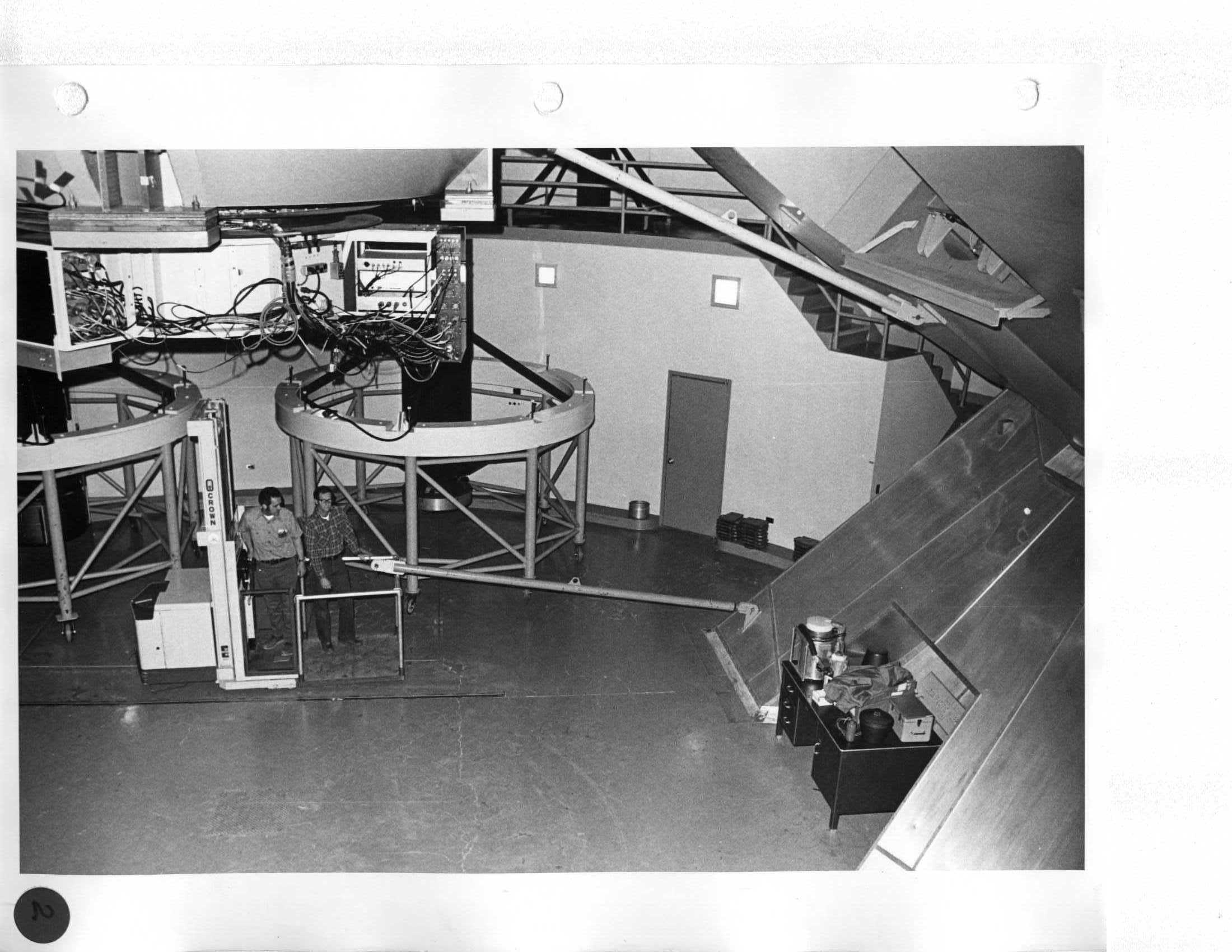
Day 1 Move Coude third mirror onto West Mezzanine, leaving space for the Cassegrain tub. |
|
5  Ron, ? |
Day 1 Move Coude third mirror onto West Mezzanine, leaving space for the Cassegrain tub. |
|
6  |
Day 1 Move Coude third mirror onto West Mezzanine, leaving space for the Cassegrain tub. |
|
7 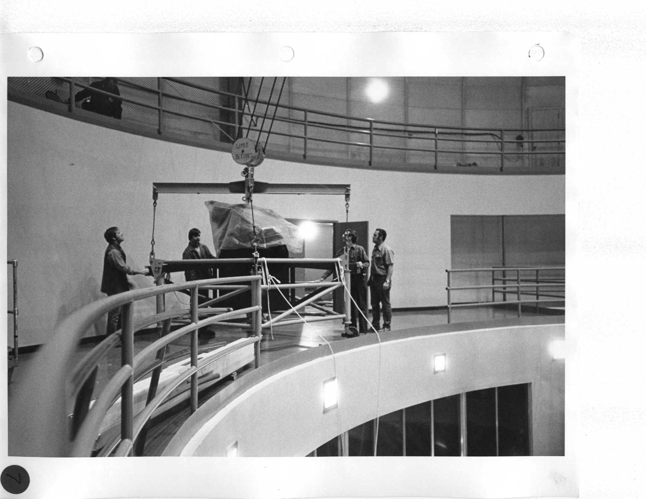 Ken Deich, ?, Len, Ron |
Day 1 Move Coude third mirror onto West Mezzanine, leaving space for the Cassegrain tub. |
|
8 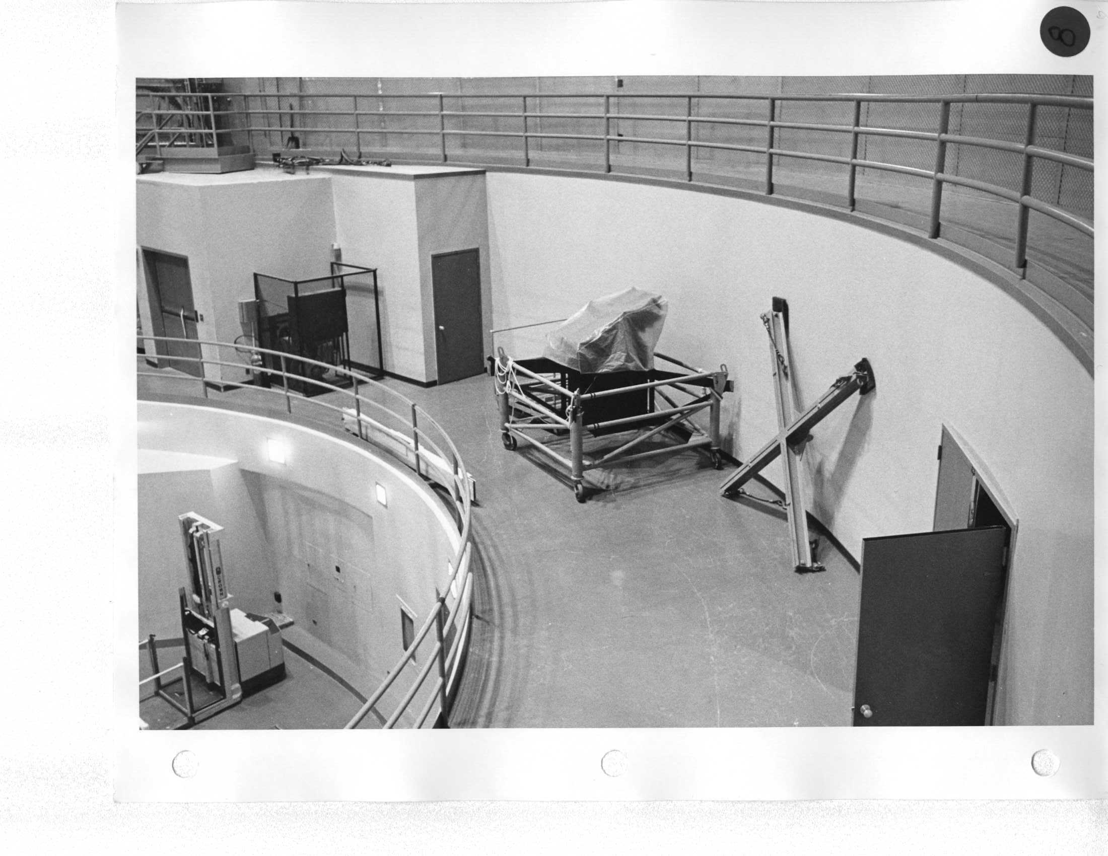 |
Day 1 Rereeve Bridge Crane hook to #2 position. |
|
9  |
Day 1 Rereeve Bridge Crane hook to #2 position. |
|
10 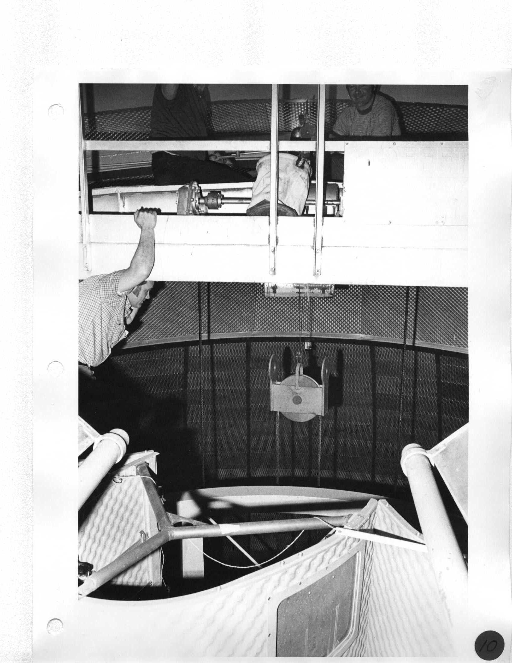 Ron, ?, ? |
Day 1 Rereeve Bridge Crane hook to #2 position. |
|
11  |
Day 1 Disconnect 5-ton hook, but don't hook up 15-ton hook until position #2 is completed. |
|
12 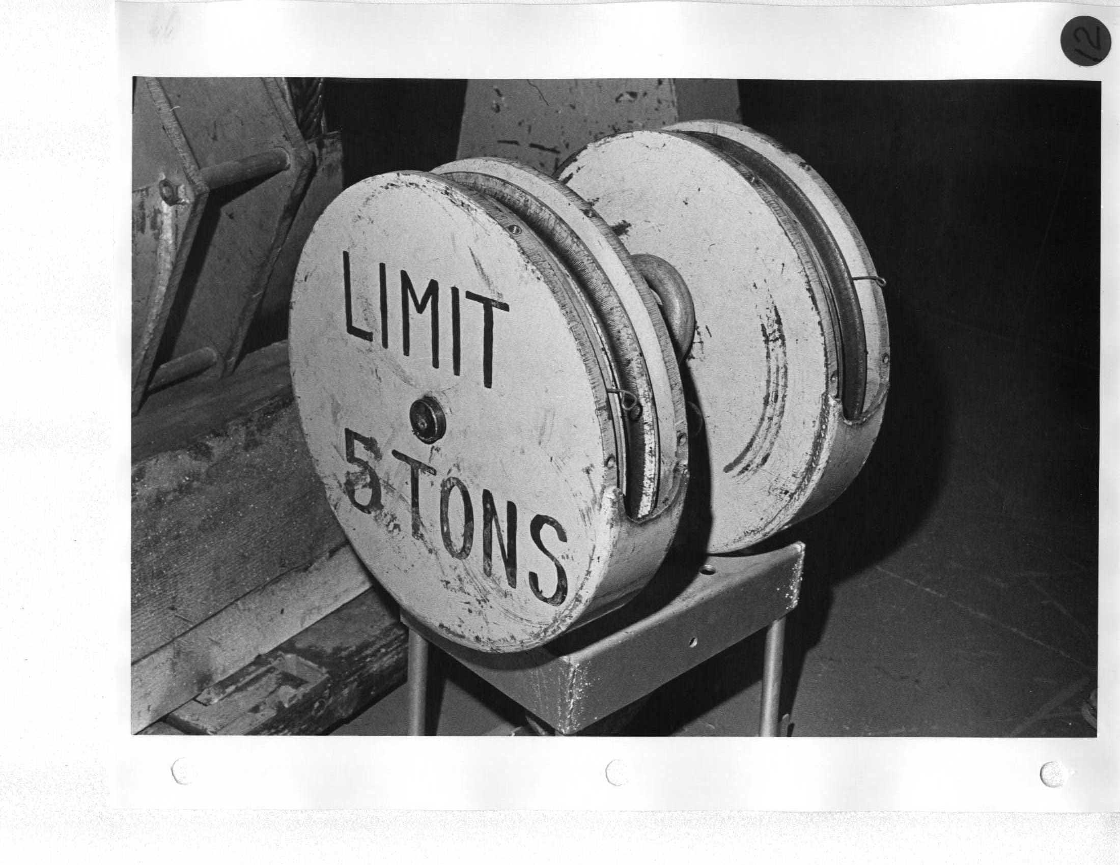 |
Day 1 Disconnect 5-ton hook, but don't hook up 15-ton hook until position #2 is completed. |
|
13 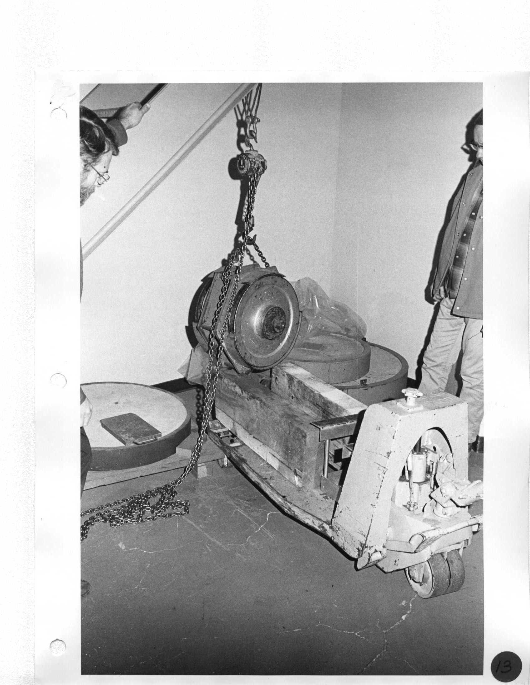 |
Day 1 Disconnect 5-ton hook, but don't hook up 15-ton hook until position #2 is completed. |
|
14 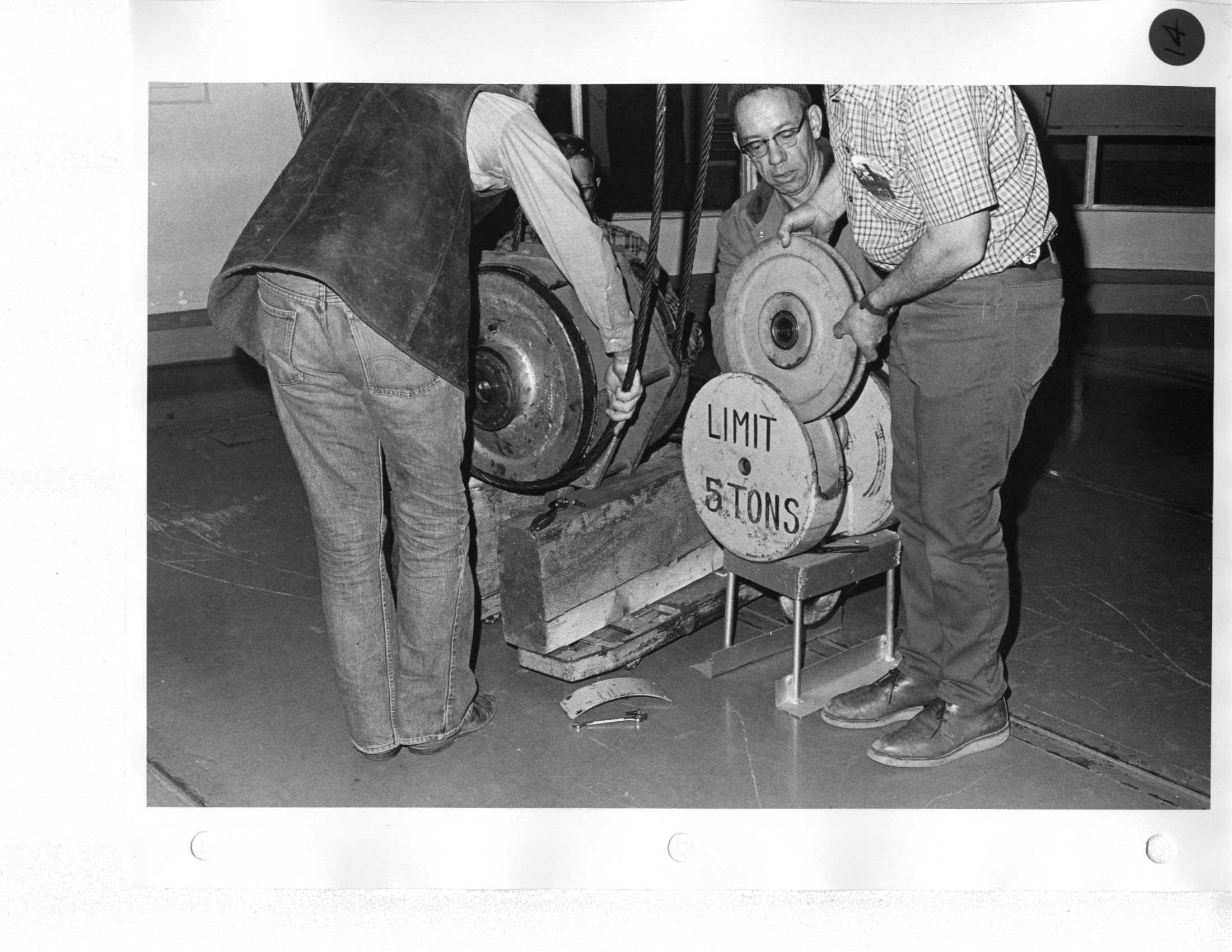 Ken, Ron |
Day 1 Disconnect 5-ton hook, but don't hook up 15-ton hook until position #2 is completed. |
|
15 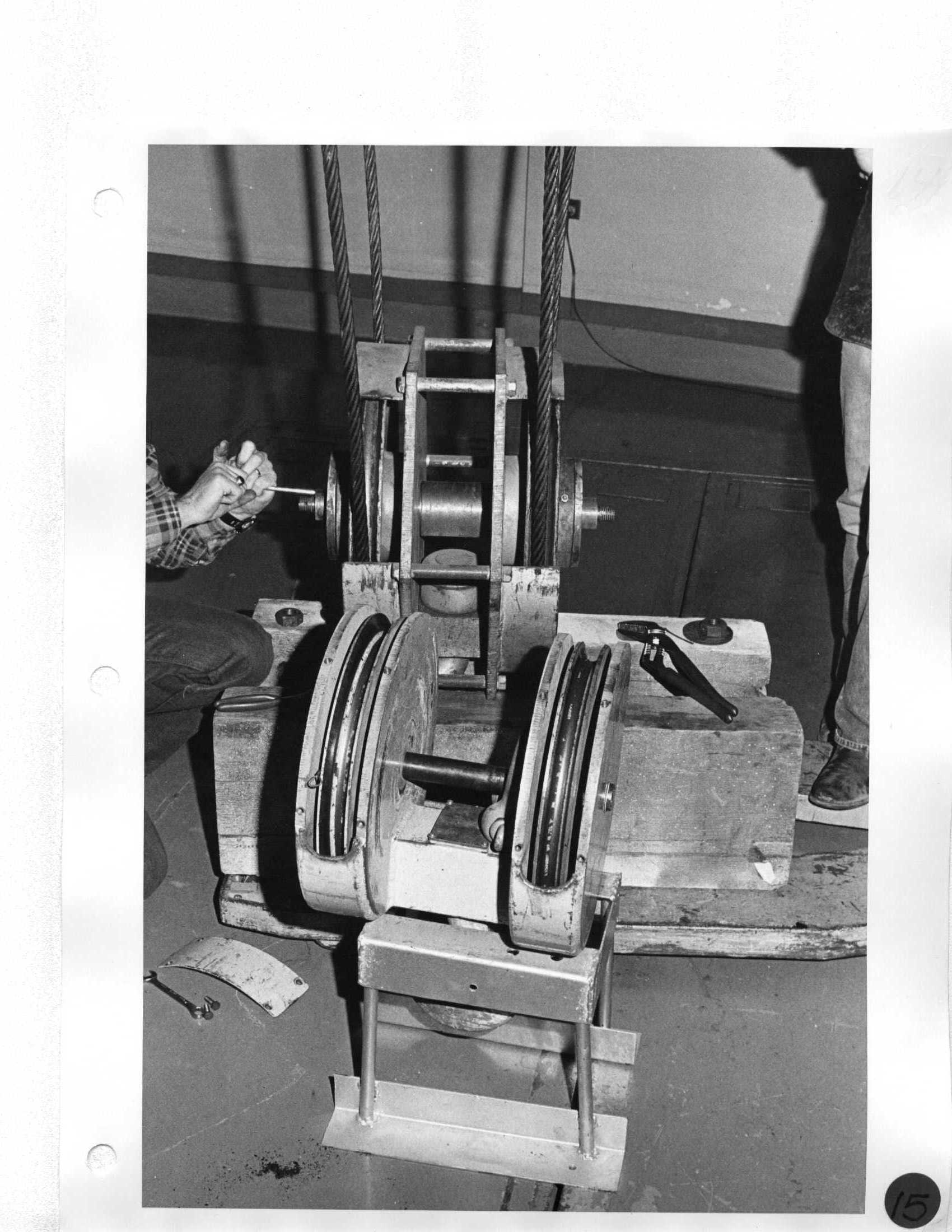 Len |
Day 1 Disconnect 5-ton hook, but don't hook up 15-ton hook until position #2 is completed. |
|
16 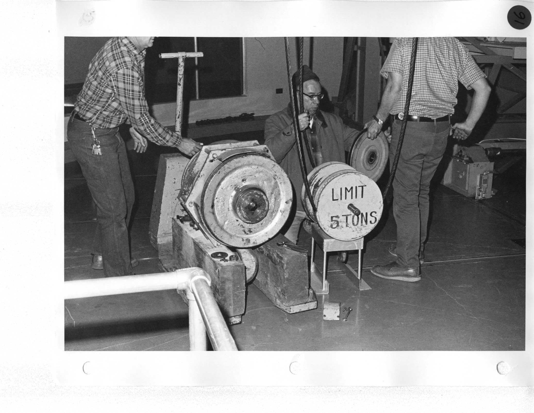 Len, Ron |
Day 1 Install mirror handling platform extensions; north-1, south-2 |
|
17 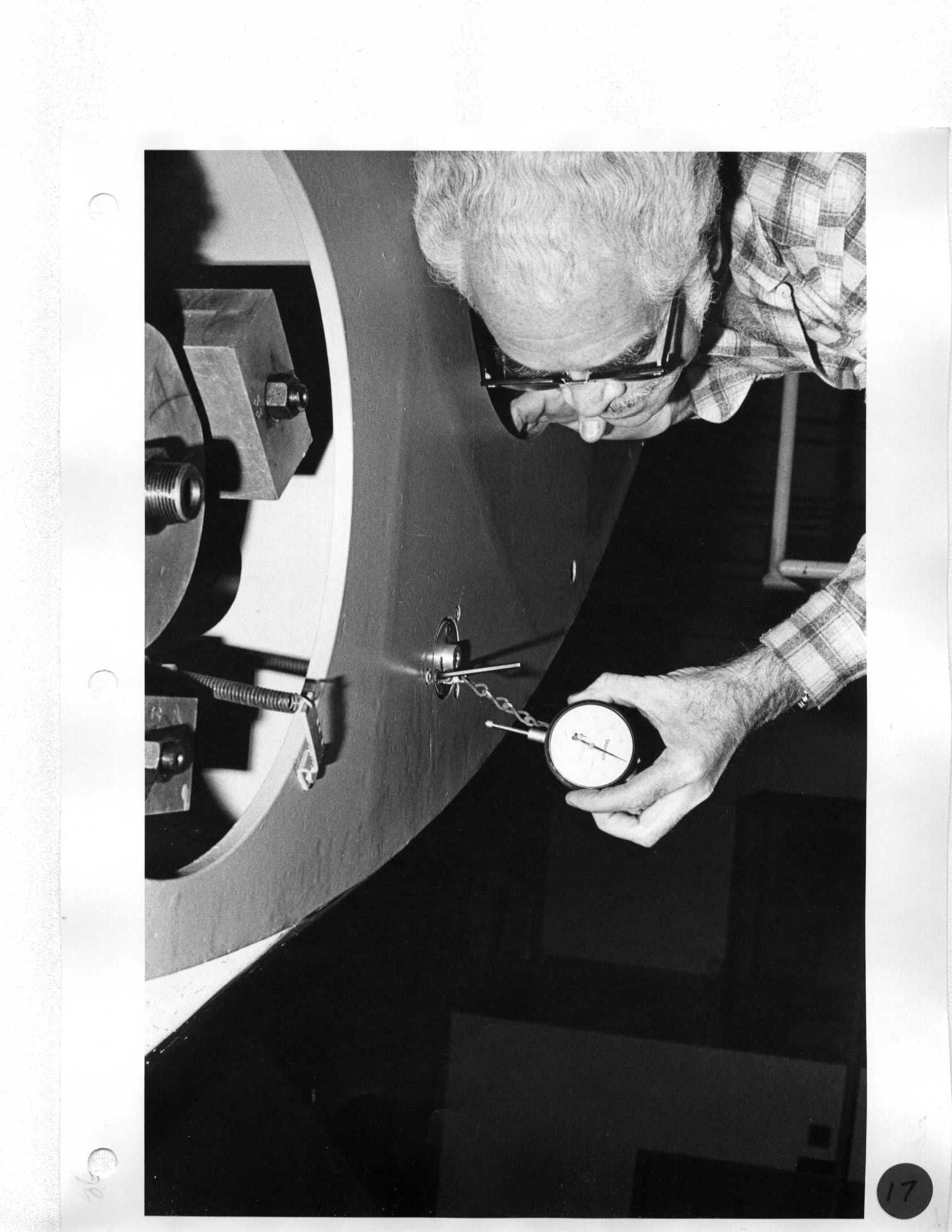 Howard Cowan |
Day 1 Install mirror handling platform extensions; north-1, south-2 |
Day 8 Remove two South platform extensions. |
18 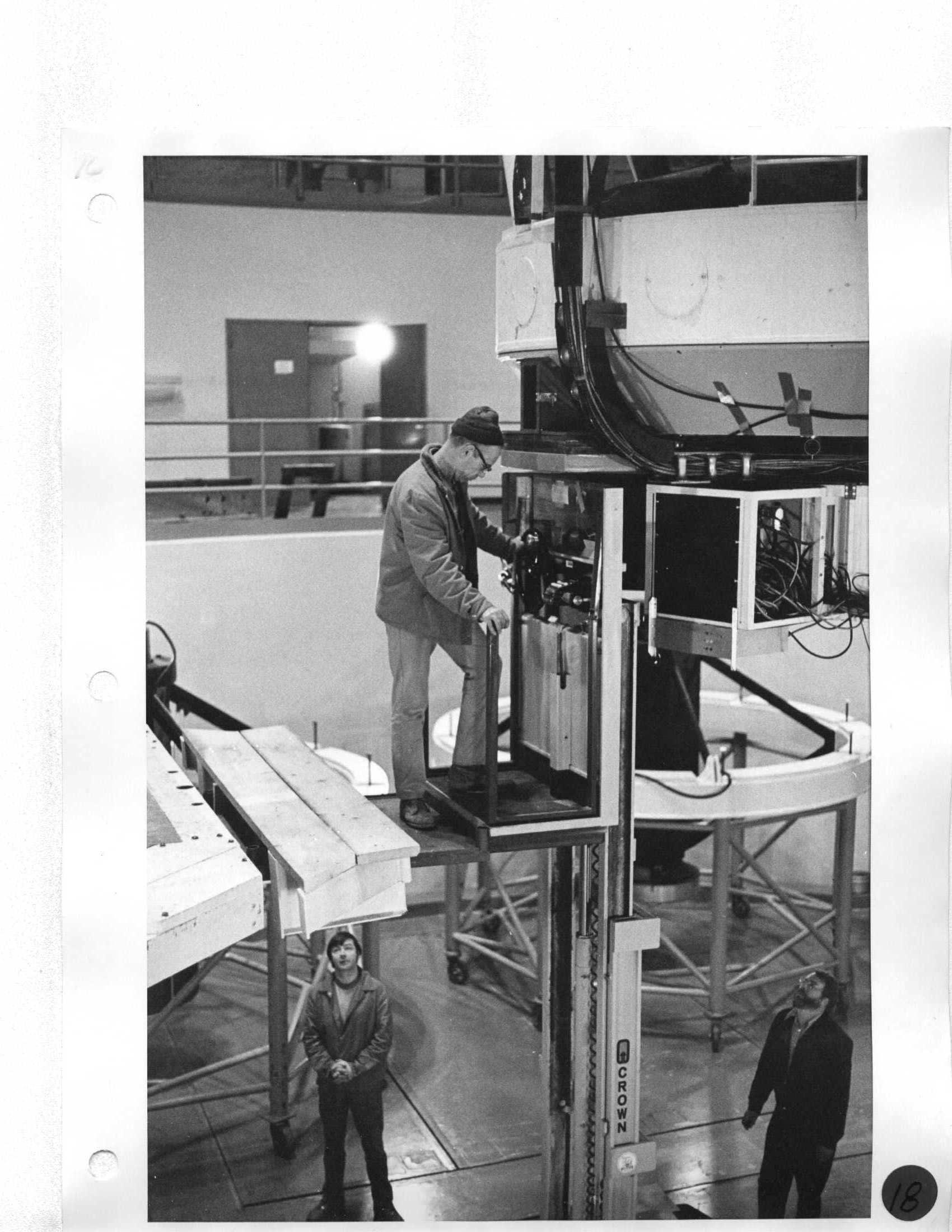 |
Day 1 Install mirror handling platform extensions; north-1, south-2 |
Day 8 Remove two South platform extensions. |
19 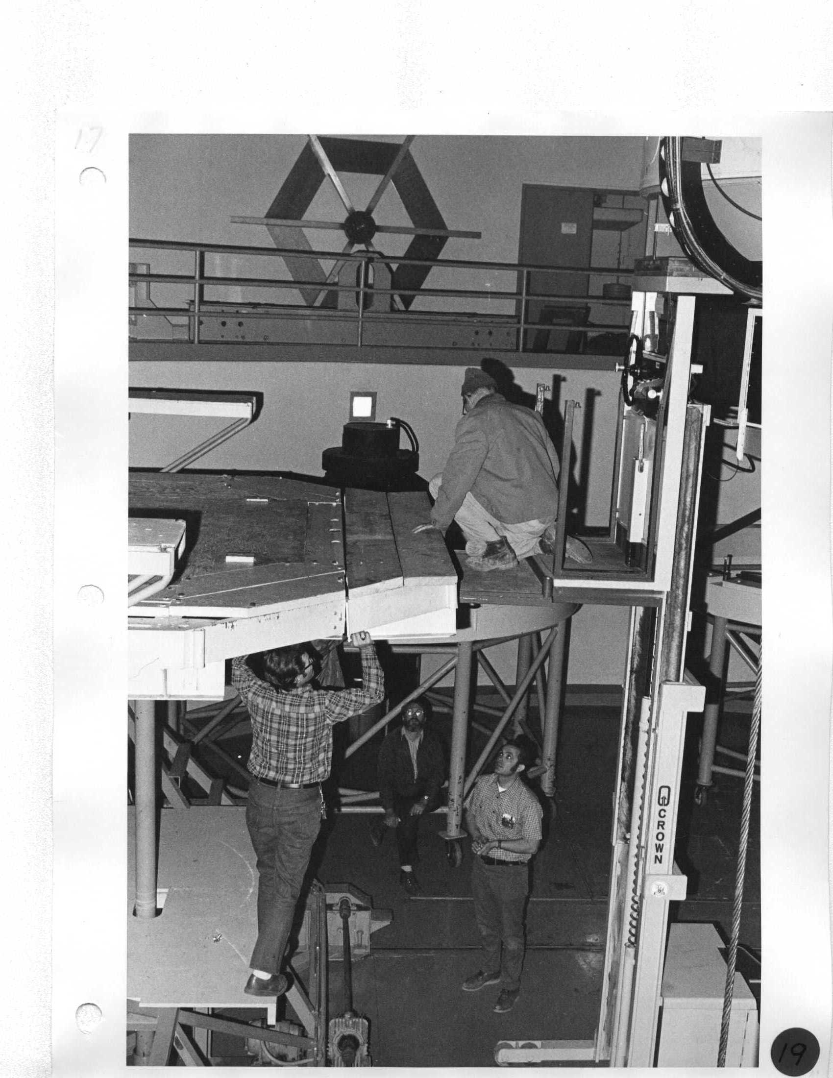 Len, Ron |
Day 1 Remove counterweight assemblies with Crown lift and store on East observing floor curb. |
Day 8 Install four counterweights on telescope with Crown lift. |
20 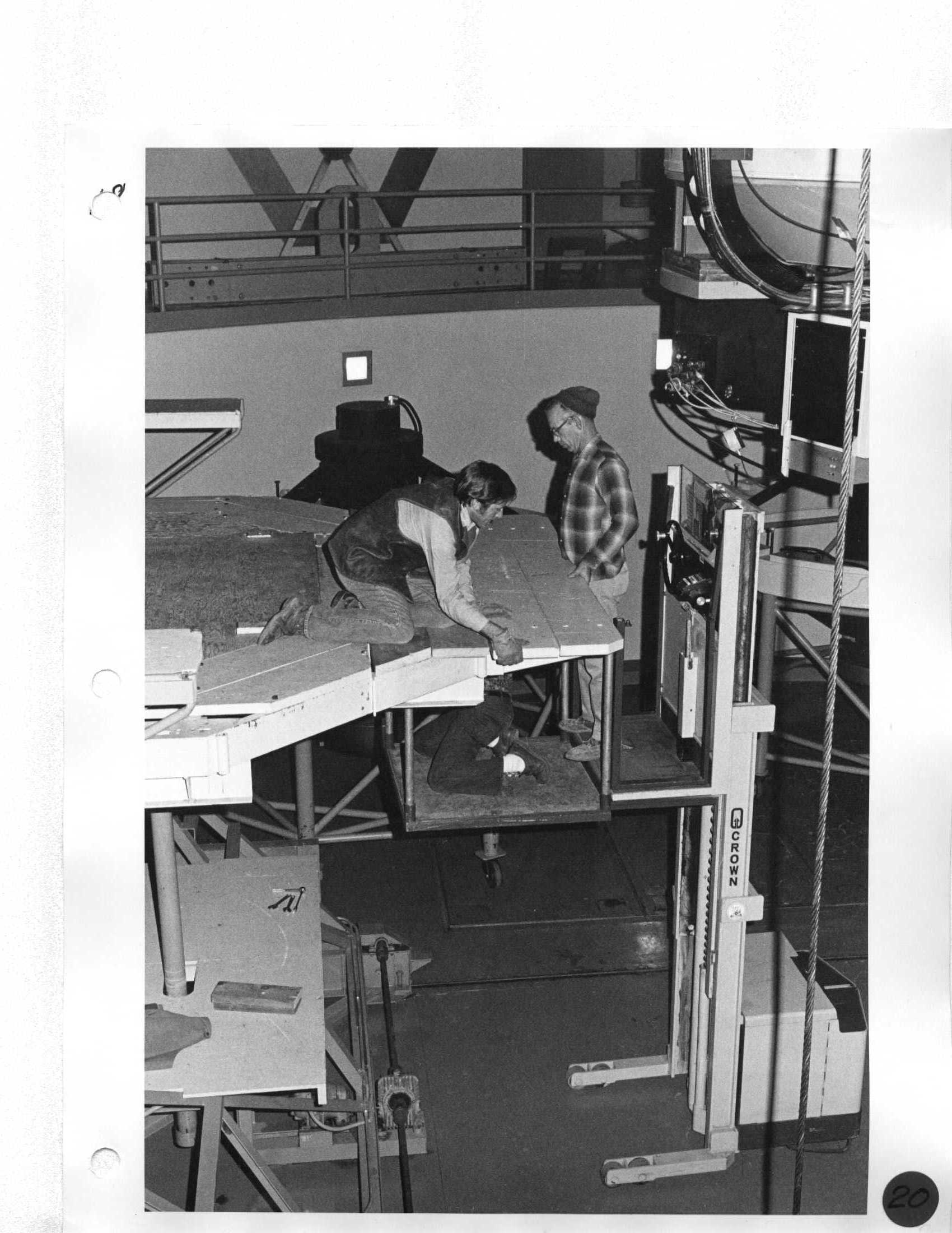 Ken, Len |
Day 1 Remove counterweight assemblies with Crown lift and store on East observing floor curb. |
Day 8 Install four counterweights on telescope with Crown lift. |
21 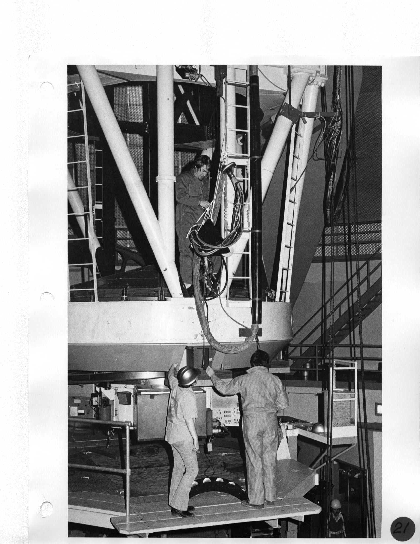 De Clarke, Erich Horn, Neal Jern |
Day 1 Remove counterweight assemblies with Crown lift and store on East observing floor curb. |
Day 8 Install four counterweights on telescope with Crown lift. |
22 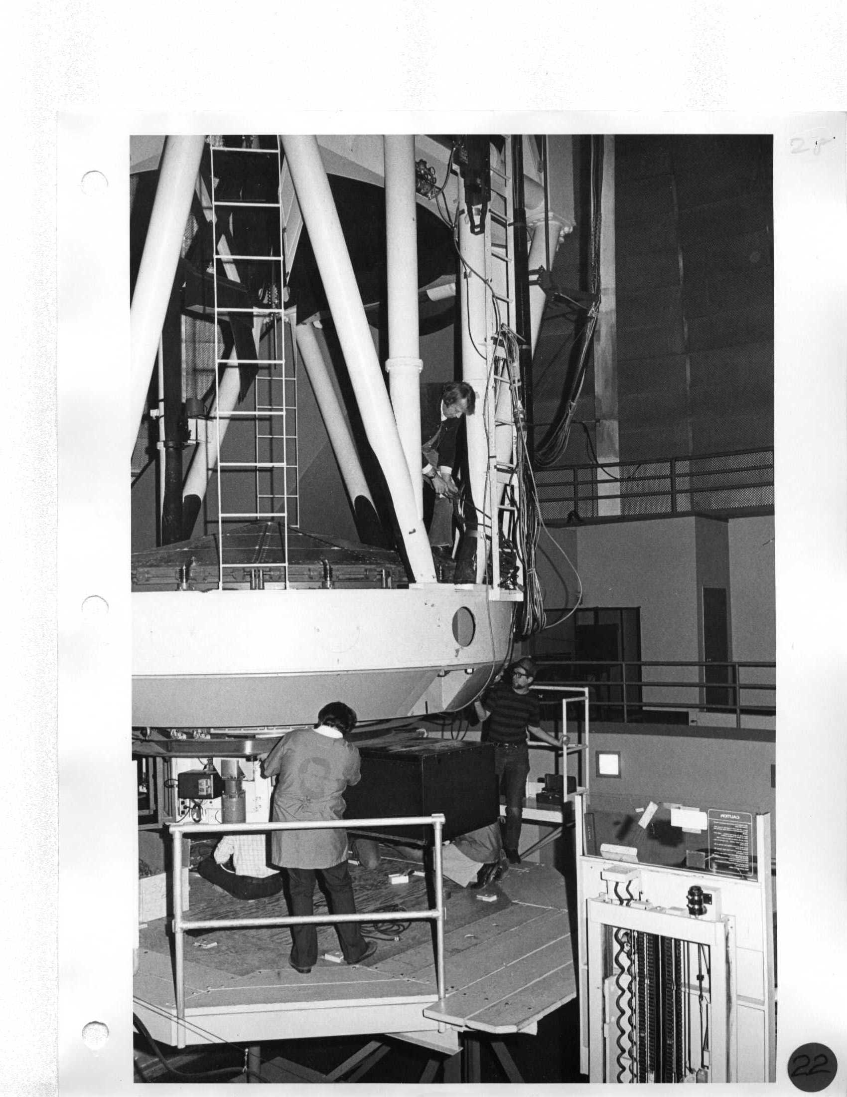 Howard, Neal, Bill Brown |
Day 1 Remove counterweight assemblies with Crown lift and store on East observing floor curb. |
Day 8 Install tub: A. Screw and torque 12 insulated hex head cap screws (special wrench with one man-power). B. Position and bolt on cable trough. C. Install X-Y stage. D. Install camera stage. E. Install electronics. |
23 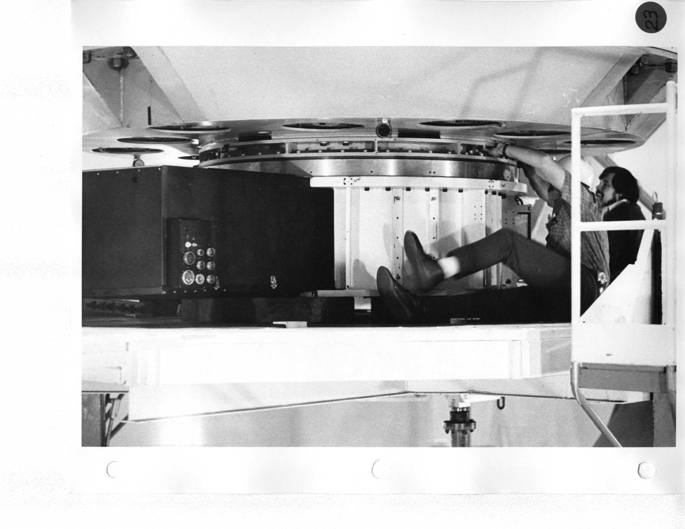 Neal |
Day 2 Remove cable trough, Cassegrain tub, and necessary electronics. Store cable trough on West Mezzanine near CAT. Store T.V. and X-Y stages in NW Mezzanine storeroom. |
Day 8 Install tub: A. Screw and torque 12 insulated hex head cap screws (special wrench with one man-power). B. Position and bolt on cable trough. C. Install X-Y stage. D. Install camera stage. E. Install electronics. |
24 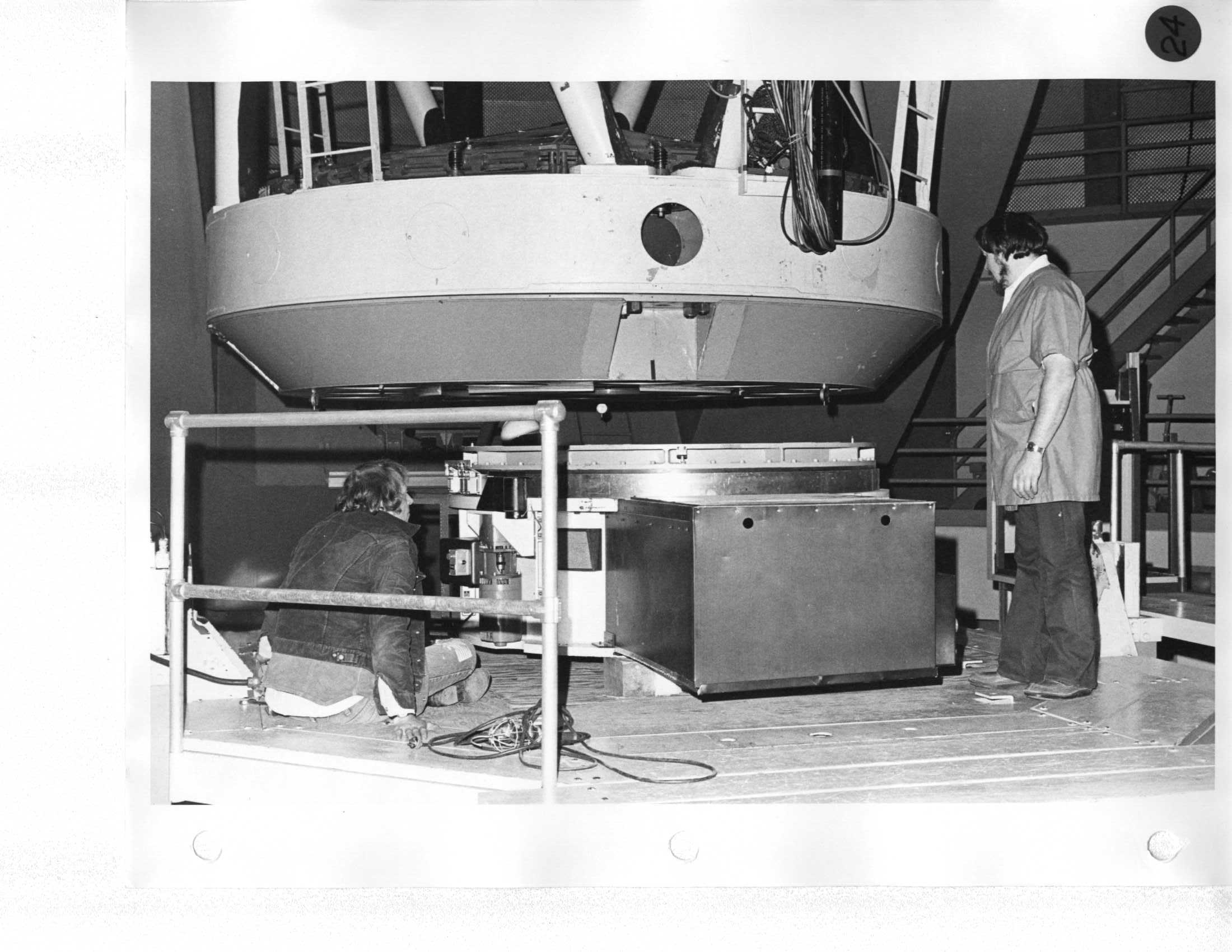 Neal |
Day 2 Remove cable trough, Cassegrain tub, and necessary electronics. Store cable trough on West Mezzanine near CAT. Store T.V. and X-Y stages in NW Mezzanine storeroom. |
Day 8 Install tub: A. Screw and torque 12 insulated hex head cap screws (special wrench with one man-power). B. Position and bolt on cable trough. C. Install X-Y stage. D. Install camera stage. E. Install electronics. |
25  Erich |
Day 2 Remove cable trough, Cassegrain tub, and necessary electronics. Store cable trough on West Mezzanine near CAT. Store T.V. and X-Y stages in NW Mezzanine storeroom. |
Day 8 Install tub: A. Screw and torque 12 insulated hex head cap screws (special wrench with one man-power). B. Position and bolt on cable trough. C. Install X-Y stage. D. Install camera stage. E. Install electronics. |
26  Neal, De |
Day 2 Remove cable trough, Cassegrain tub, and necessary electronics. Store cable trough on West Mezzanine near CAT. Store T.V. and X-Y stages in NW Mezzanine storeroom. |
Day 8 Install tub: A. Screw and torque 12 insulated hex head cap screws (special wrench with one man-power). B. Position and bolt on cable trough. C. Install X-Y stage. D. Install camera stage. E. Install electronics. |
27  |
Day 2 Remove cable trough, Cassegrain tub, and necessary electronics. Store cable trough on West Mezzanine near CAT. Store T.V. and X-Y stages in NW Mezzanine storeroom. |
Day 8 Install tub: A. Screw and torque 12 insulated hex head cap screws (special wrench with one man-power). B. Position and bolt on cable trough. C. Install X-Y stage. D. Install camera stage. E. Install electronics. |
28  Mike Owens, Erich, De, Neal |
Day 2 Remove cable trough, Cassegrain tub, and necessary electronics. Store cable trough on West Mezzanine near CAT. Store T.V. and X-Y stages in NW Mezzanine storeroom. |
Day 8 Install tub: A. Screw and torque 12 insulated hex head cap screws (special wrench with one man-power). B. Position and bolt on cable trough. C. Install X-Y stage. D. Install camera stage. E. Install electronics. |
29  Neal, De |
Day 2 Remove cable trough, Cassegrain tub, and necessary electronics. Store cable trough on West Mezzanine near CAT. Store T.V. and X-Y stages in NW Mezzanine storeroom. |
Day 8 Install tub: A. Screw and torque 12 insulated hex head cap screws (special wrench with one man-power). B. Position and bolt on cable trough. C. Install X-Y stage. D. Install camera stage. E. Install electronics. |
30  Neal |
Day 2 Remove cable trough, Cassegrain tub, and necessary electronics. Store cable trough on West Mezzanine near CAT. Store T.V. and X-Y stages in NW Mezzanine storeroom. |
Day 8 Position tub on platform and center under telescope. |
31 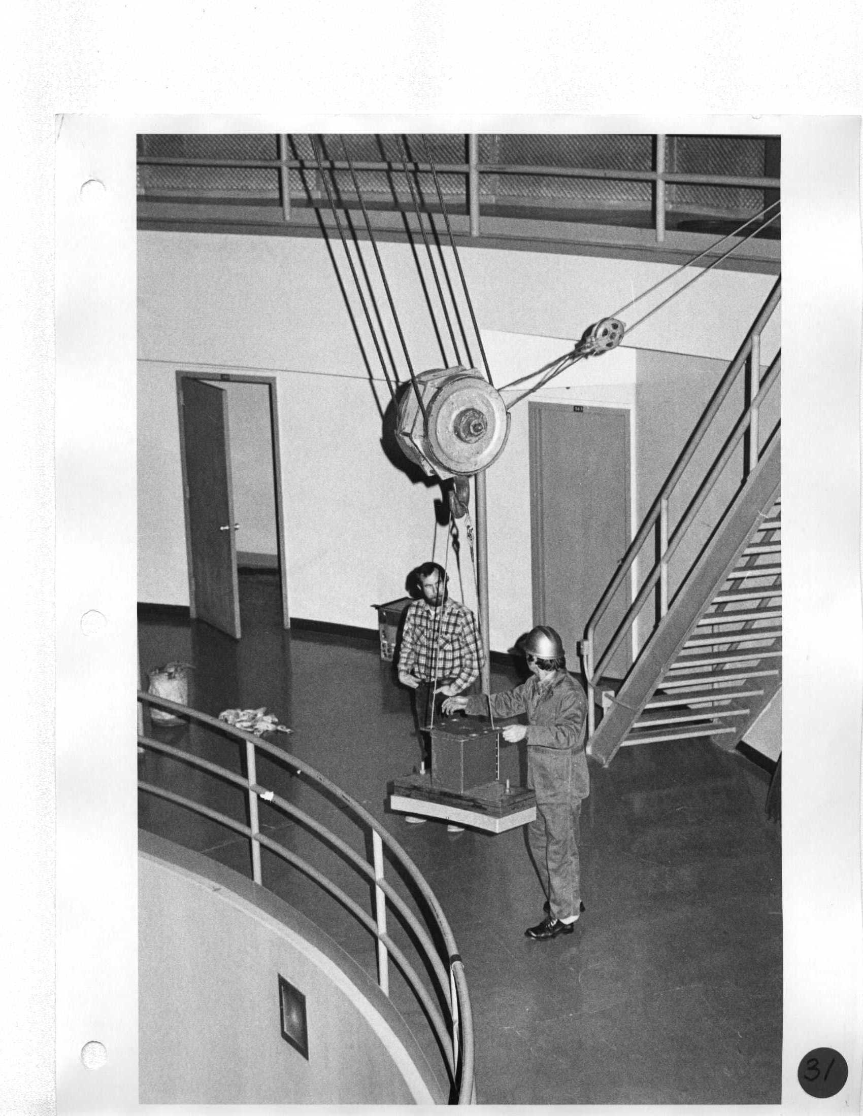 Jack Osborne |
Day 2 Store Cassegrain tub on West Mezzanine next to third mirror. Use outhaul. |
Day 8 Position tub on platform and center under telescope |
32 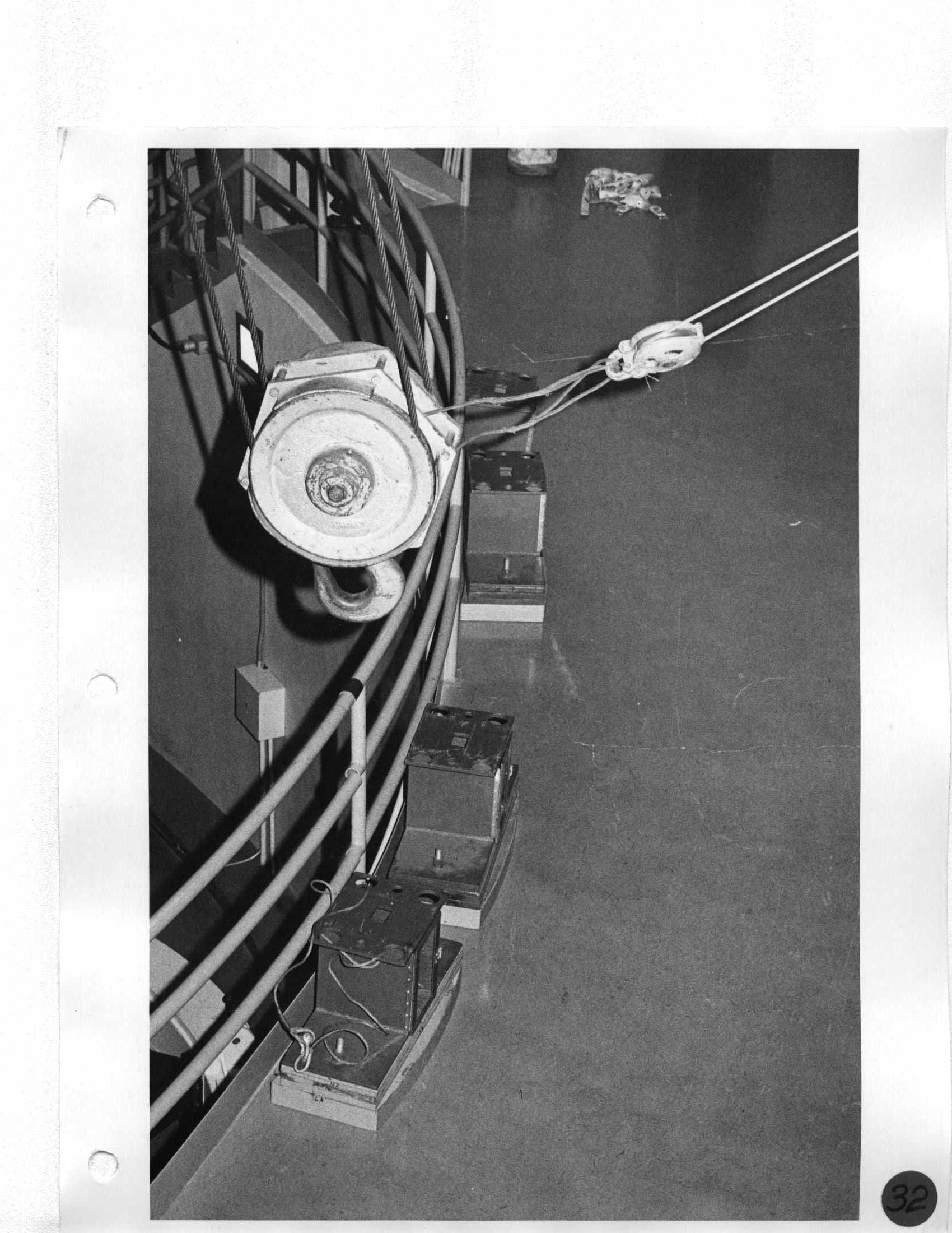 |
Day 2 Store Cassegrain tub on West Mezzanine next to third mirror. Use outhaul. |
|
33 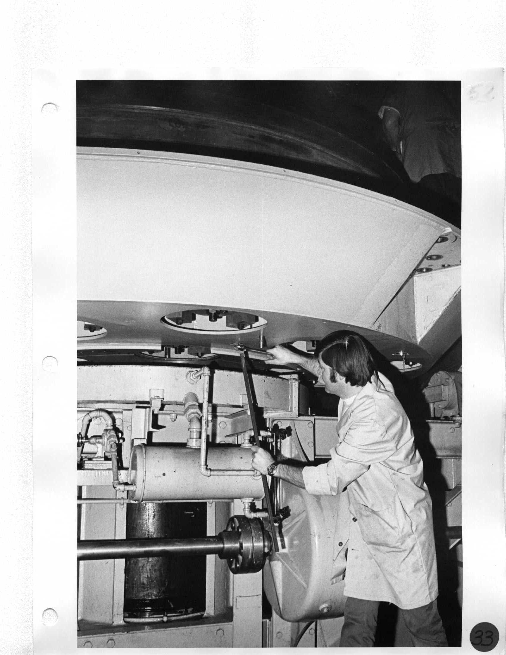 |
Day 2 Remove flooring on mirror handling platform. |
Day 7 Install mirror supports and remove edge arcs. |
34 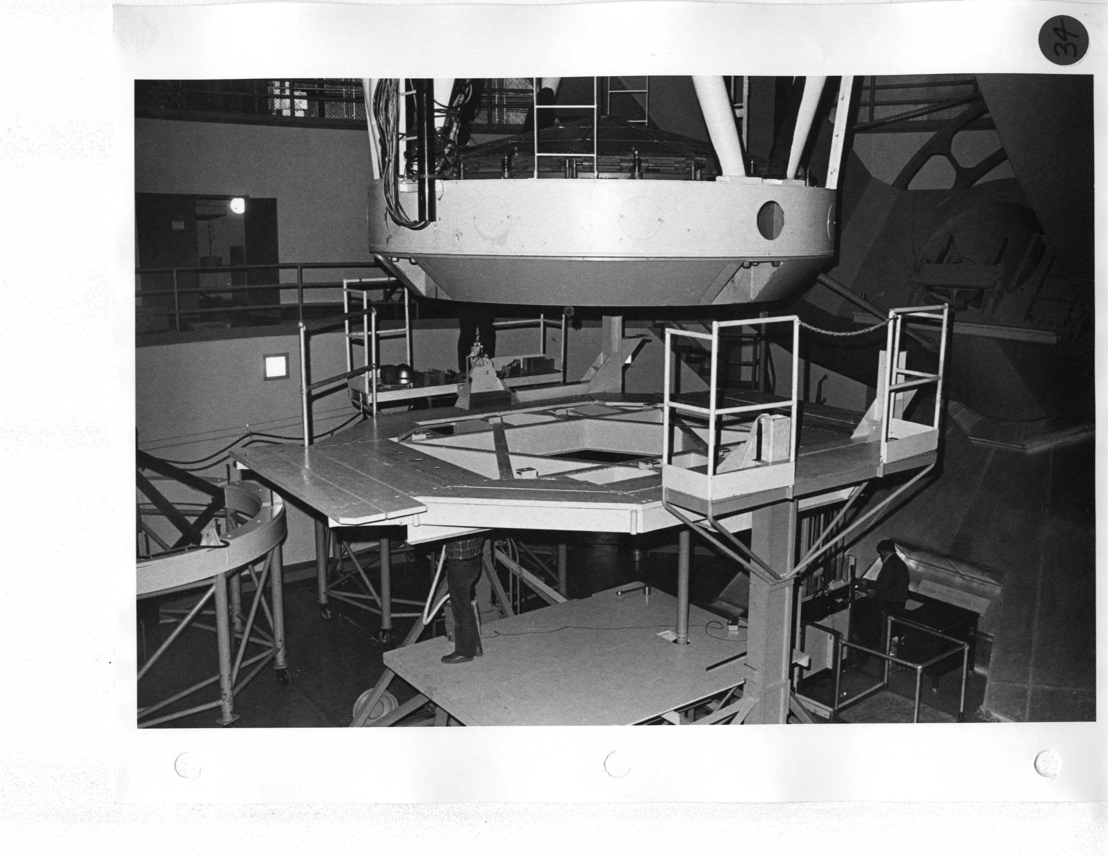 |
Day 2 Position platform under cell; jack East side of platform up and slide 3/8" shims under wheel. |
Day 7 Drive mirror handling platform under telescope; jack East side of platform and install 3/8" spacers. |
35 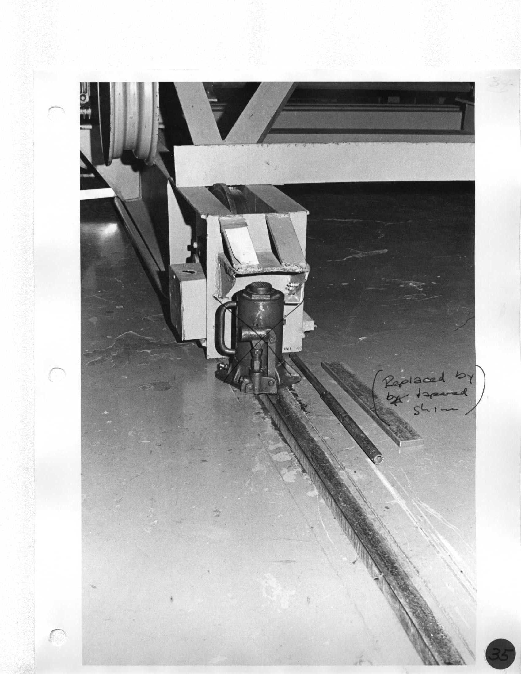 |
Day 2 Position platform under cell; jack East side of platform up and slide 3/8" shims under wheel. |
Day 7 Drive mirror handling platform under telescope; jack East side of platform and install 3/8" spacers. |
36 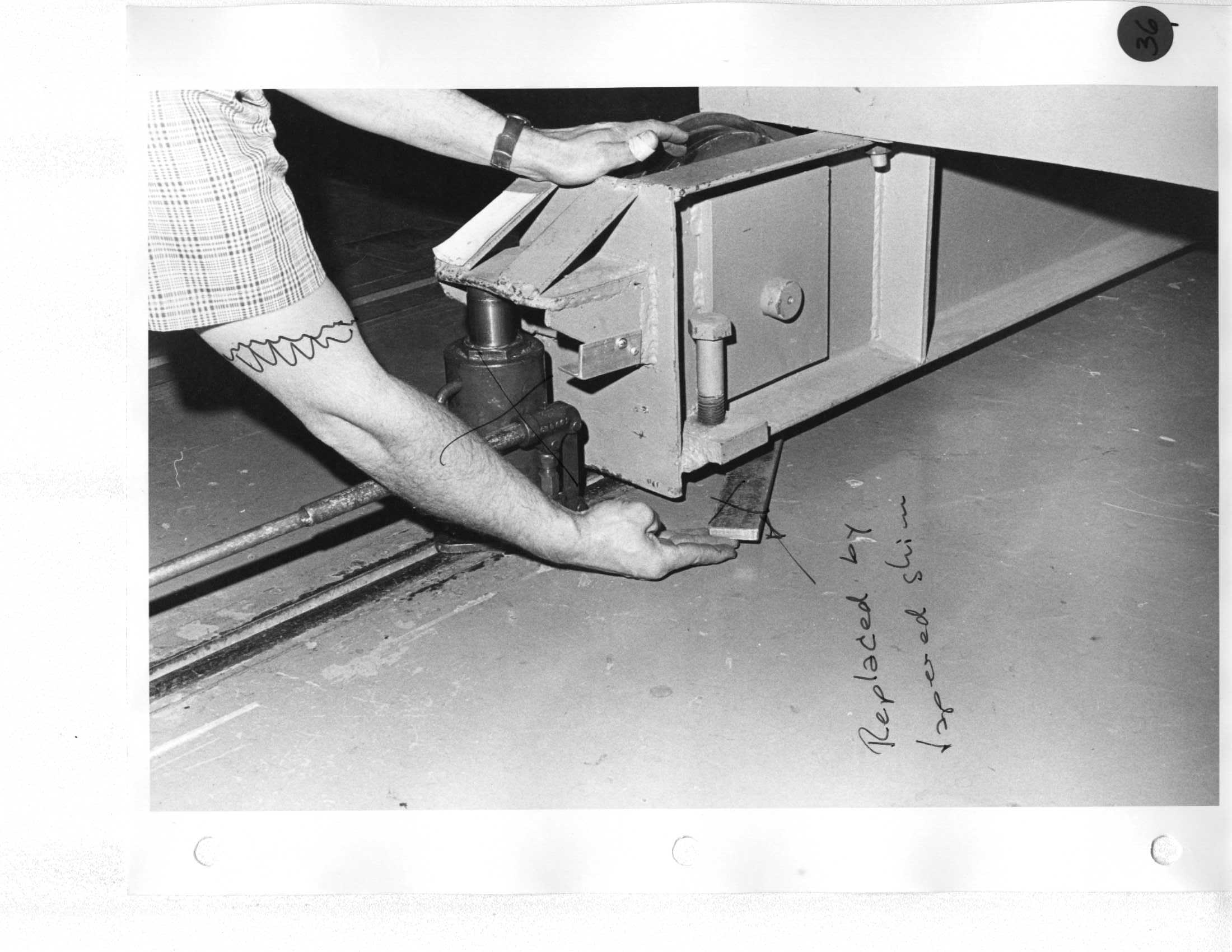 |
Day 2 Record dial indicator readings and remove. |
Day 8 Install three dial gauges. |
37 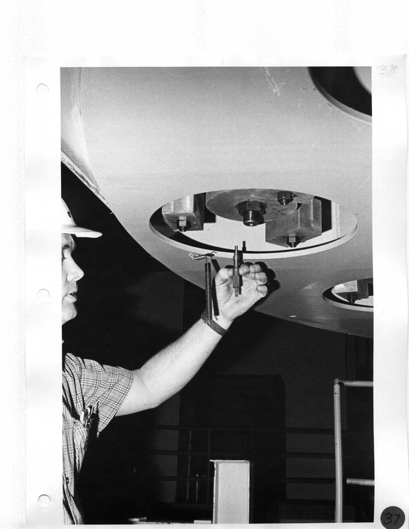 Ron |
Day 2 Remove micrometers and hold down springs. CAUTION: DO NOT CHANGE SETTINGS! Lift on counterweights to install allen wrench. |
Day 8 Collimate primary mirror. |
38 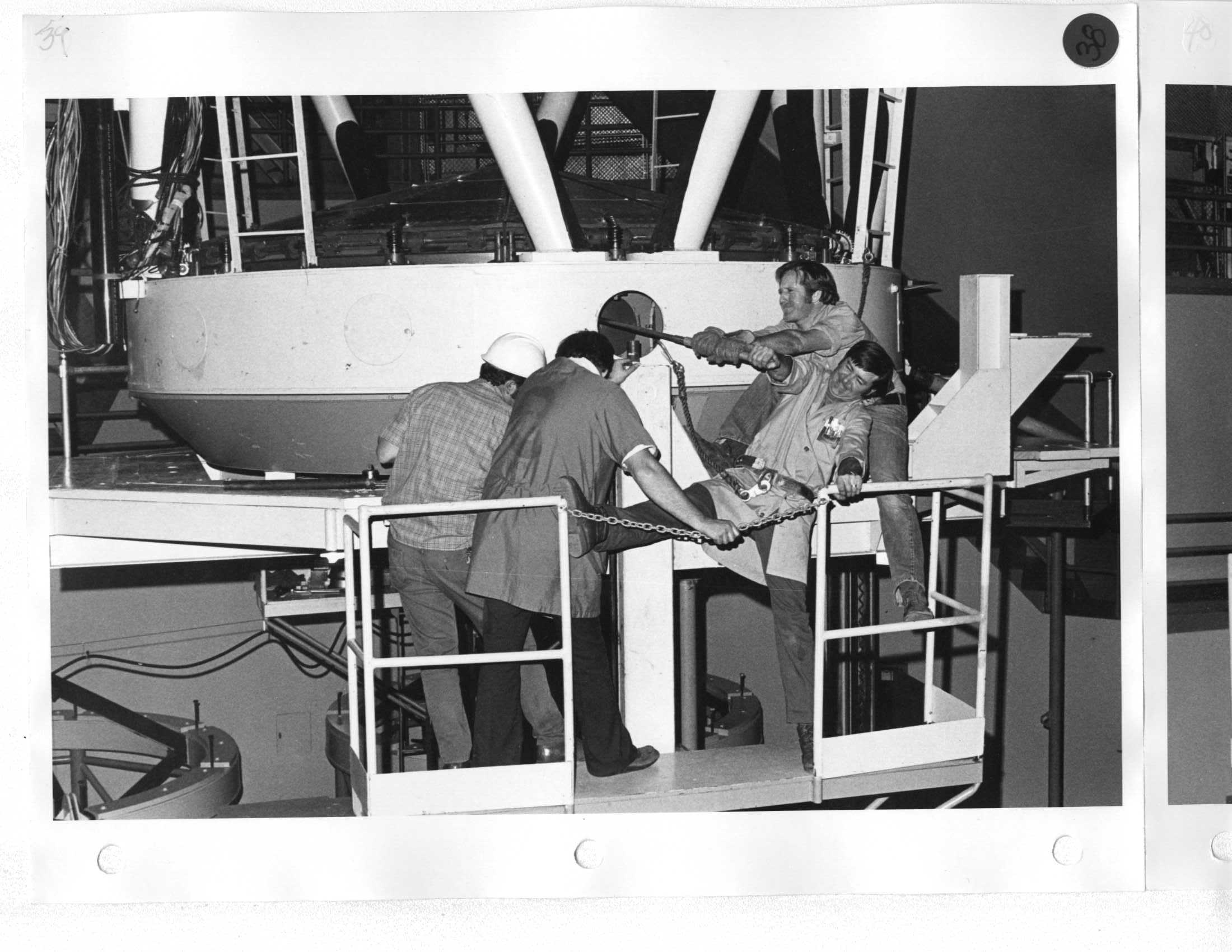 Ron, Neal, Ken |
Day 2 Remove micrometers and hold down springs. CAUTION: DO NOT CHANGE SETTINGS! Lift on counterweights to install allen wrench. |
Day 8 A. Install three micrometers and check readings; install springs between counterweights and brackets. B. Collimate primary mirror by adjusting micrometers. |
39  Neal, Ron, Ken |
Day 2 |
Day 7 Install four bolts at N-S-E-W position and torque with two man-power. |
40  Erich, Ron, Neal |
Day 2 Remove 16 bolts and nuts. Nut size: 2-3/16" and 2-1/4" |
|
41  Ken, Erich, Ron, Neal |
Day 2 Lower cell 6"; remove bottom thermistor. |
Day 7 Continue to raise mirror and install bottom thermistor. |
42  |
Day 2 Lower to down limit; remove top thermistor. |
Day 7 Raise mirror and cell high enough to install top thermistor. |
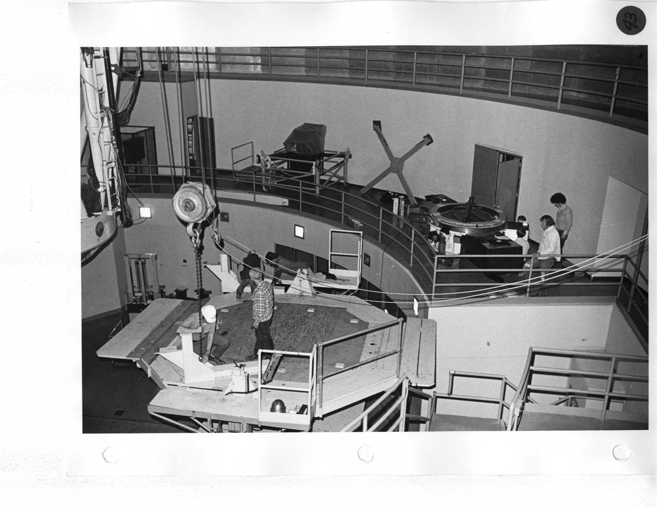
43 |
Day 2 |
|
44 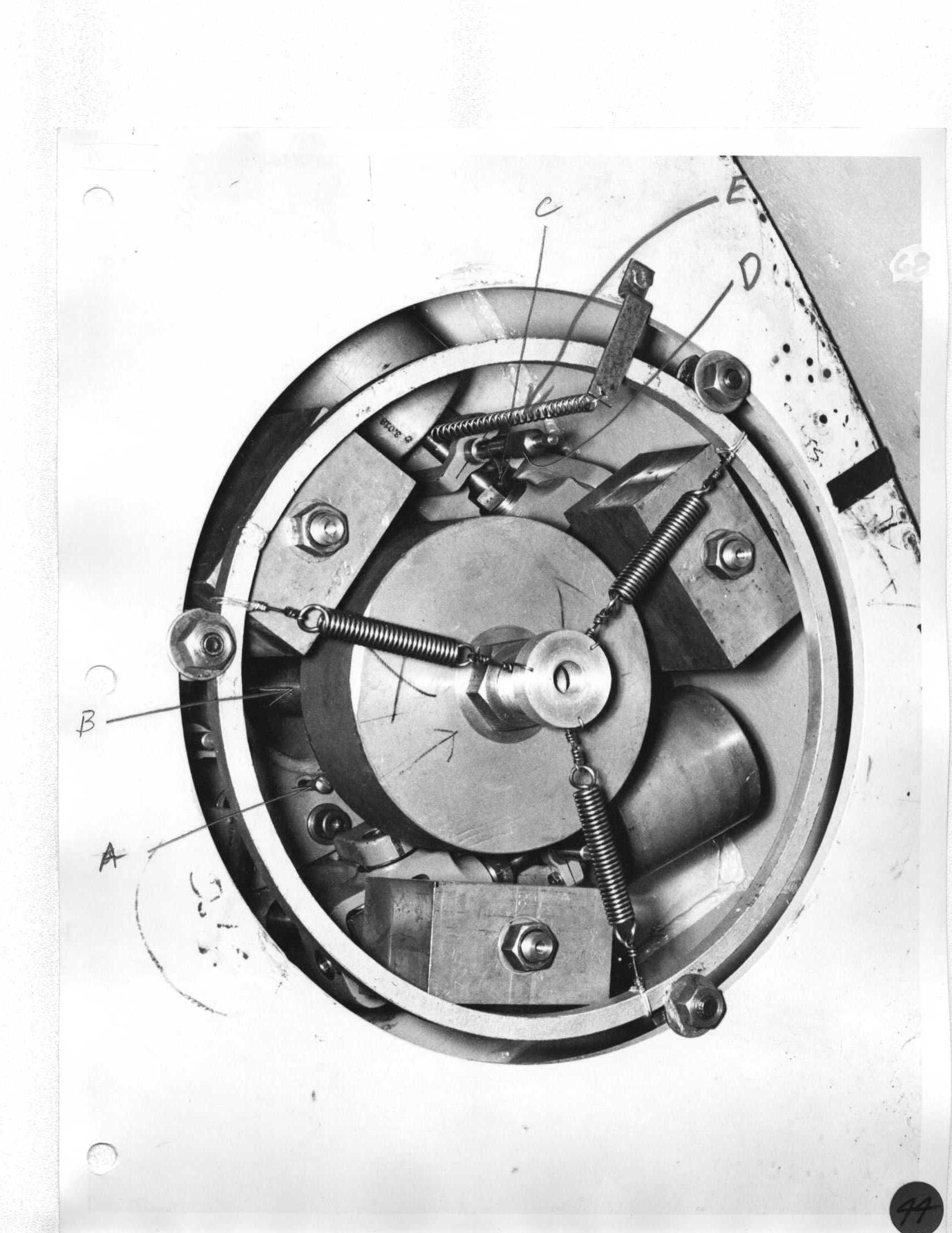 |
Day 2 Remove floor covers over optic shop; use lifting chain extensions next to platform. |
|
45 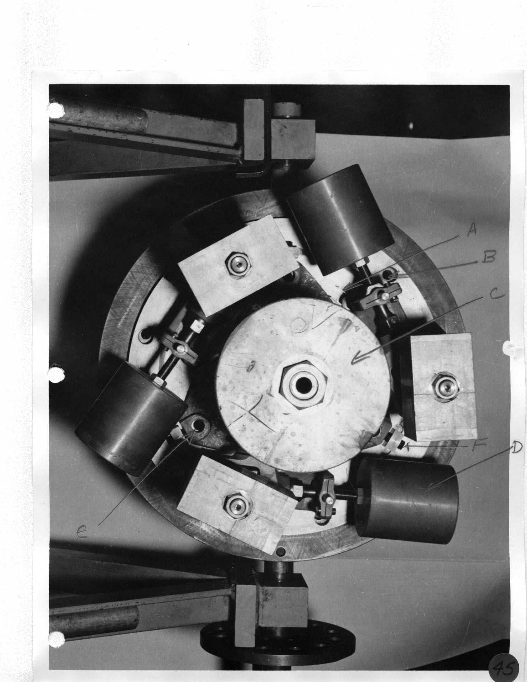 |
Day 2 Remove floor covers over optic shop; use lifting chain extensions next to platform. |
|
46 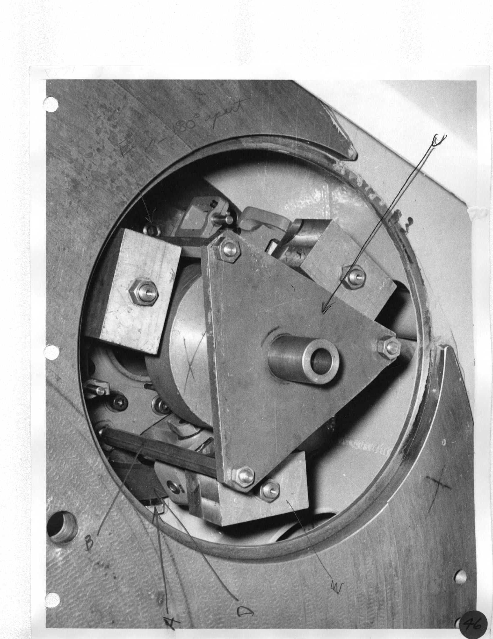 |
Day 2 Connect 2" wire cable stinger to crane hook. |
|
47 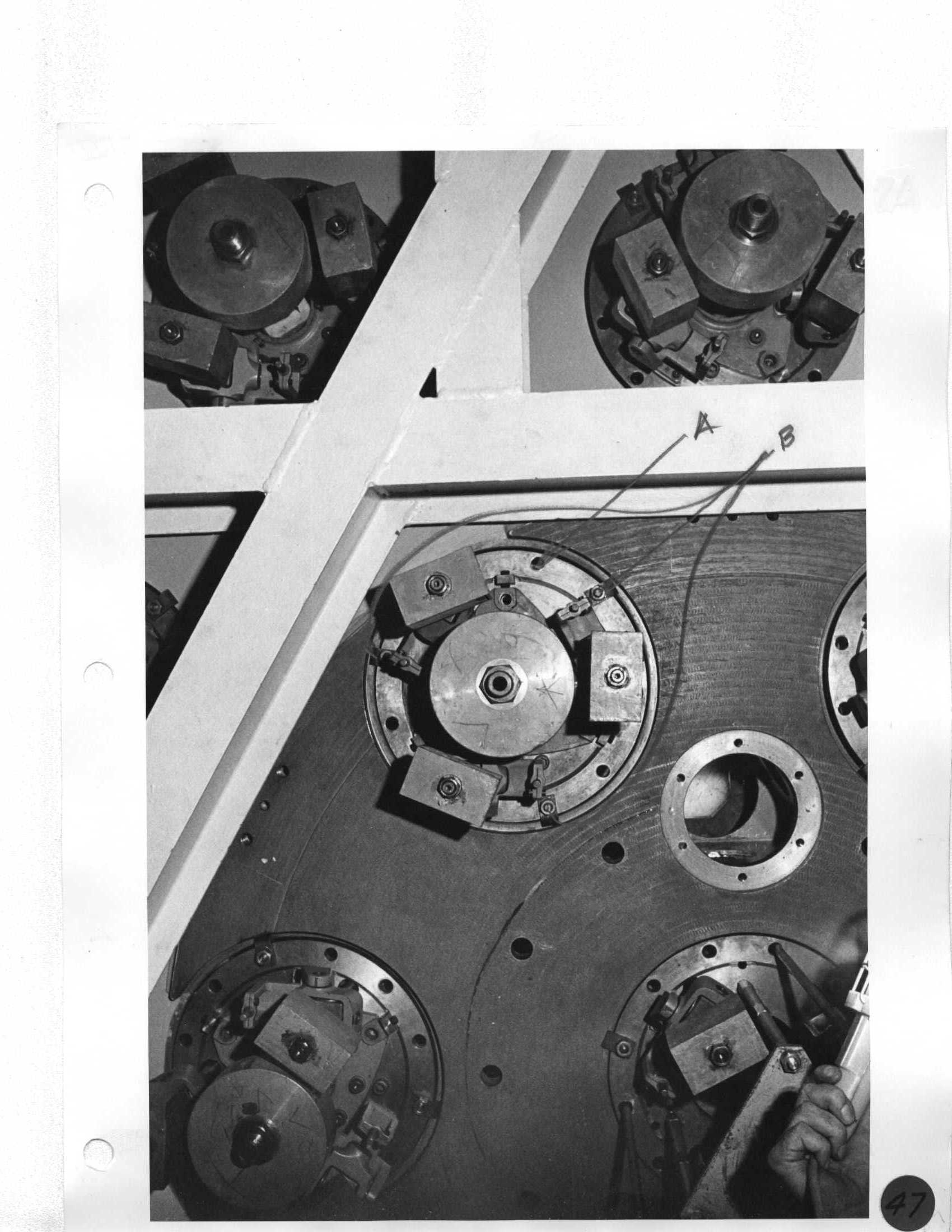 |
Day 2 Position hook over mirror and connect slings to holes closest to edge of cell. |
|
48 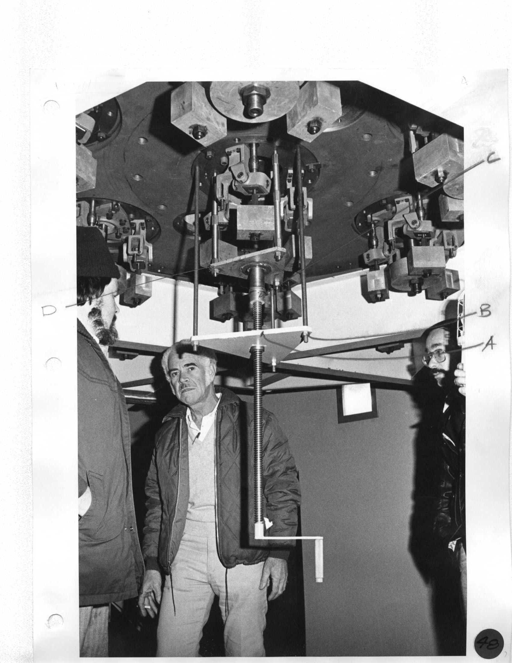 Neal, Howard, Joe |
Day 2 Position hook over mirror and connect slings to holes closest to edge of cell. Attach a rope to both sides of mirror cell for guiding; gently lift and position over grinding machine. |
|
49 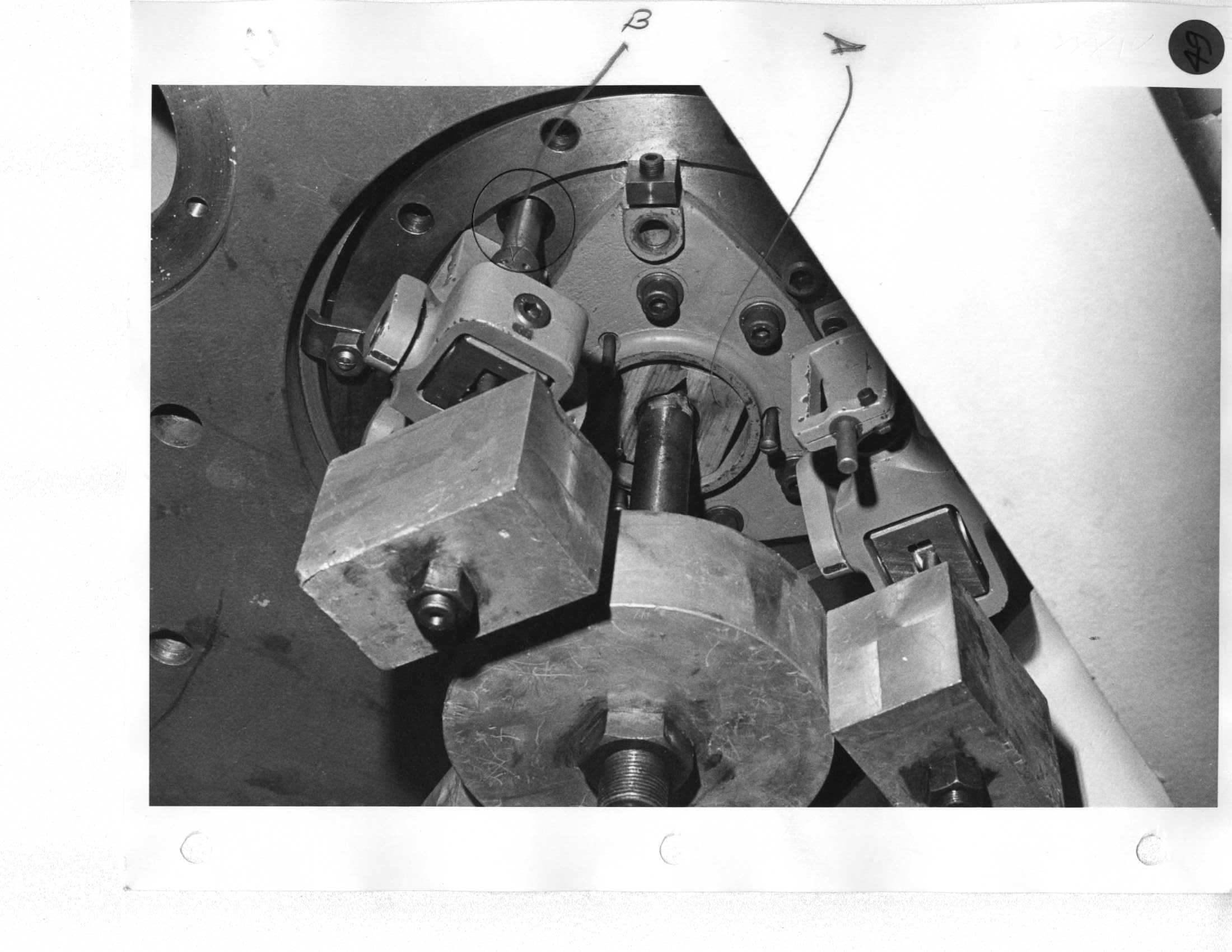 |
Day 2 Attach a rope to both sides of mirror cell for guiding; gently lift and position over grinding machine. |
|
50 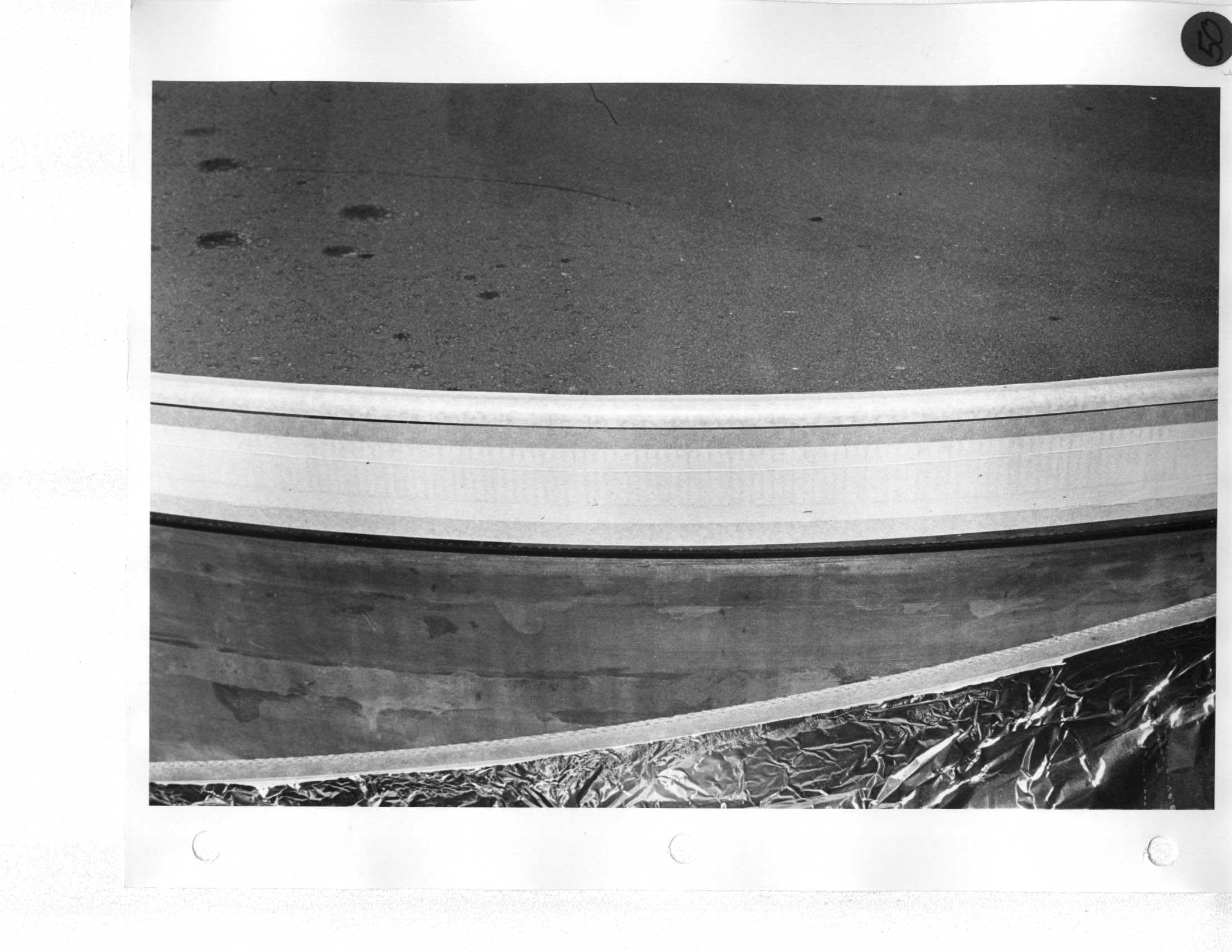 |
Day 2 Install support arms for mirror spreader bar on South end of mirror handling platform while work on mirror continues. |
|
51 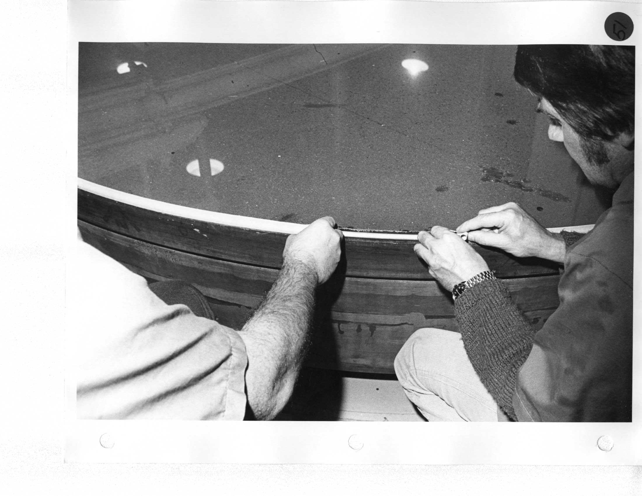 Erich |
Day 3 Screw three jacks up against the mirror (120-deg apart) with 1/2" key stock. |
|
52 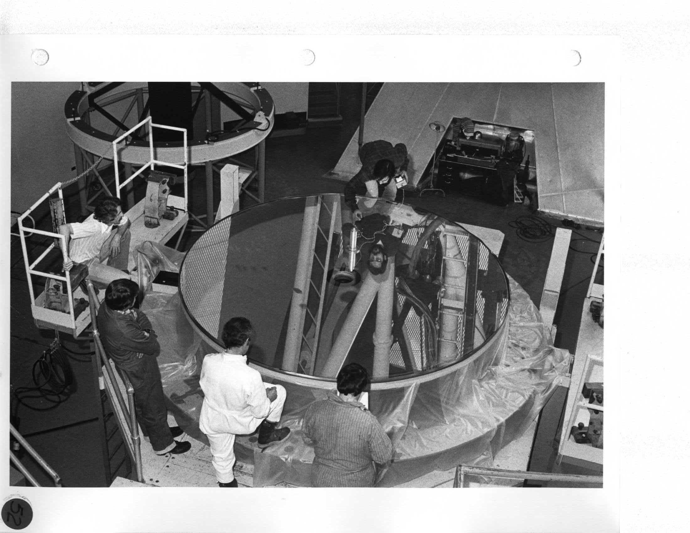 Erich, Ron, Neal, Mike |
Day 3 Rotate grinding machine table. |
|
53 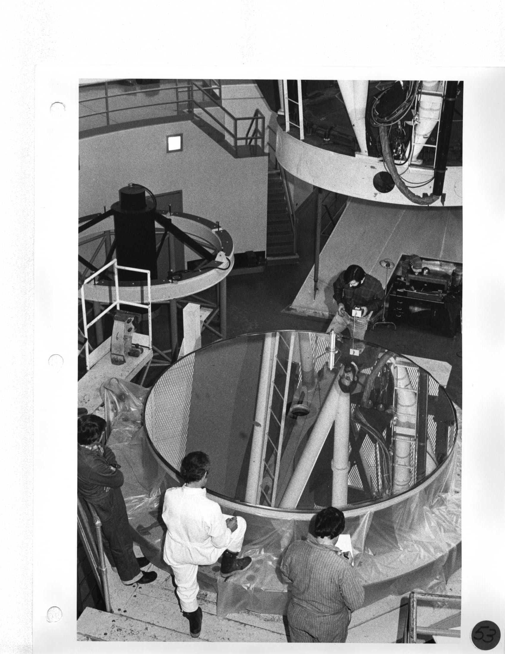 Erich, Ron, Neal, Mike |
Day 3 Test mirror surface with reflectometer. |
|
54 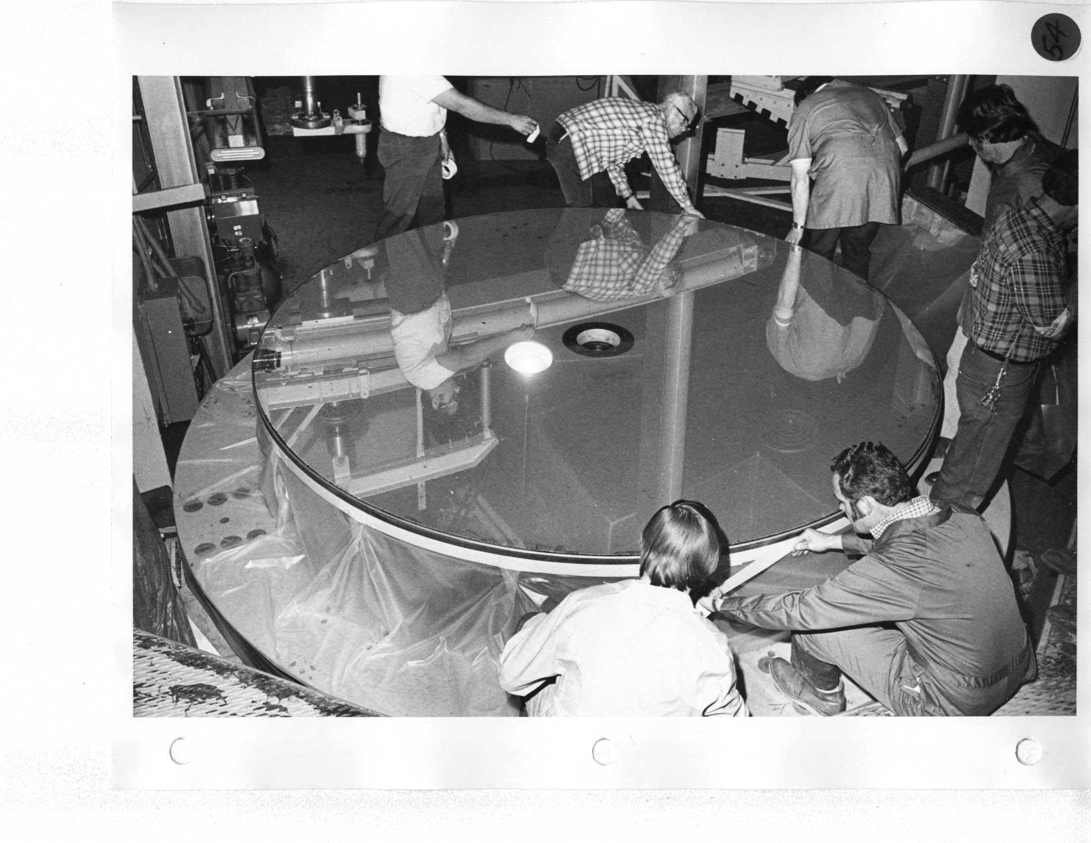 Howard, Ron, Neal, Erich |
Day 3 Remove aluminum foil, cardboard, and masking tape. |
|
55 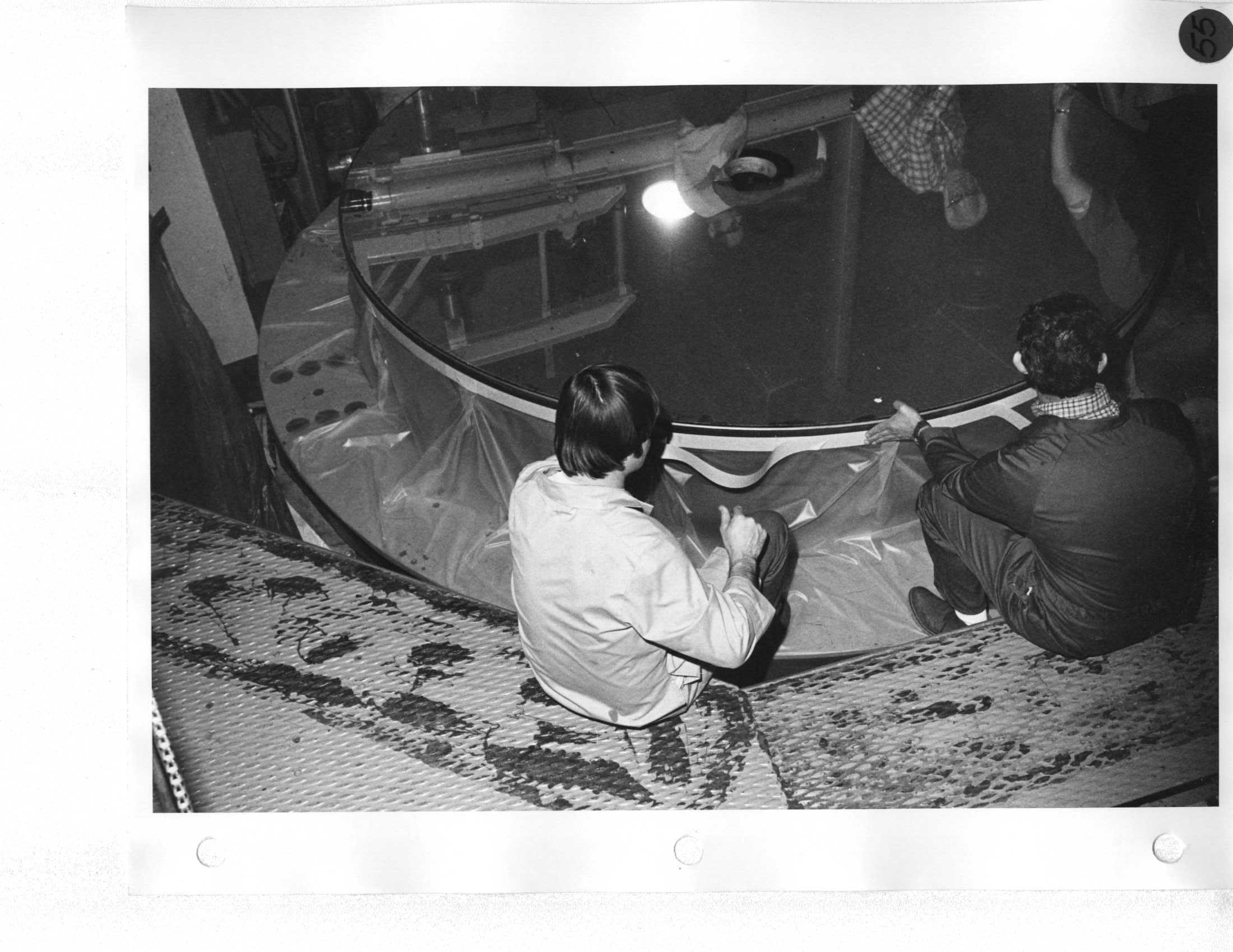 Howard, Ron |
Day 3 Remove aluminum foil, cardboard, and masking tape. |
|
56 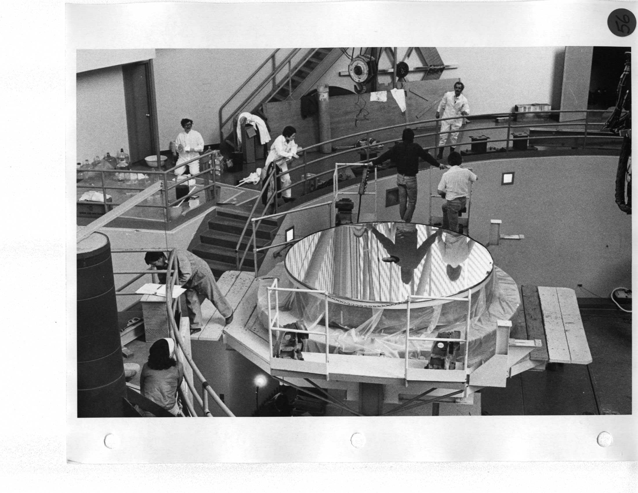 Neal, Keith Baker, De, Ron |
Day 3 Apply one wrap of 48" wide vinyl sheeting draped over edge of cell. |
|
57 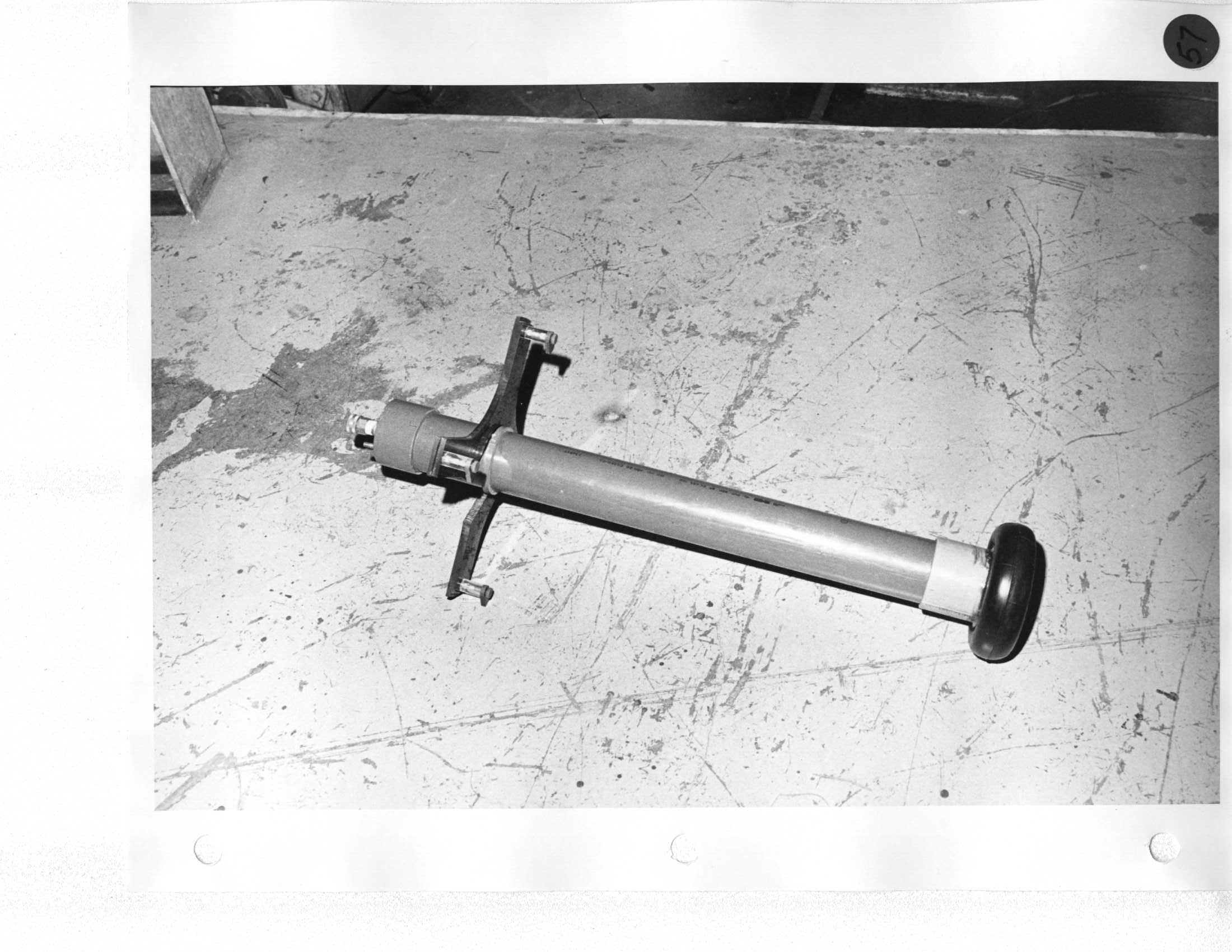 |
Day 3 Apply one wrap of double face 2" masking tape in place of cardboard. Apply one wrap of single face 2" masking tape. |
|
58 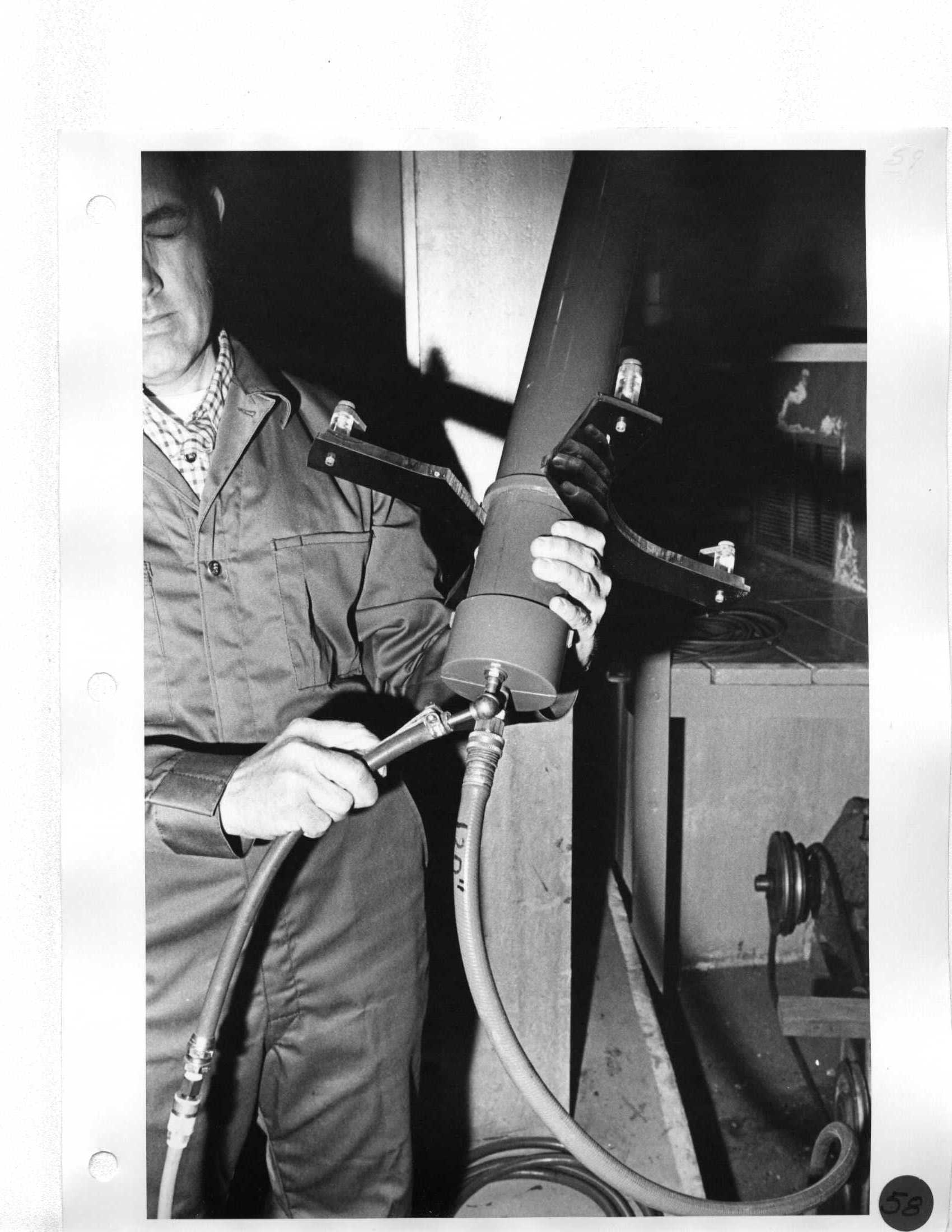 Ron |
Day 3 Install PVC drain plug in center of mirror from bottom, inflate inner tube, and connect three hangers. |
|
59 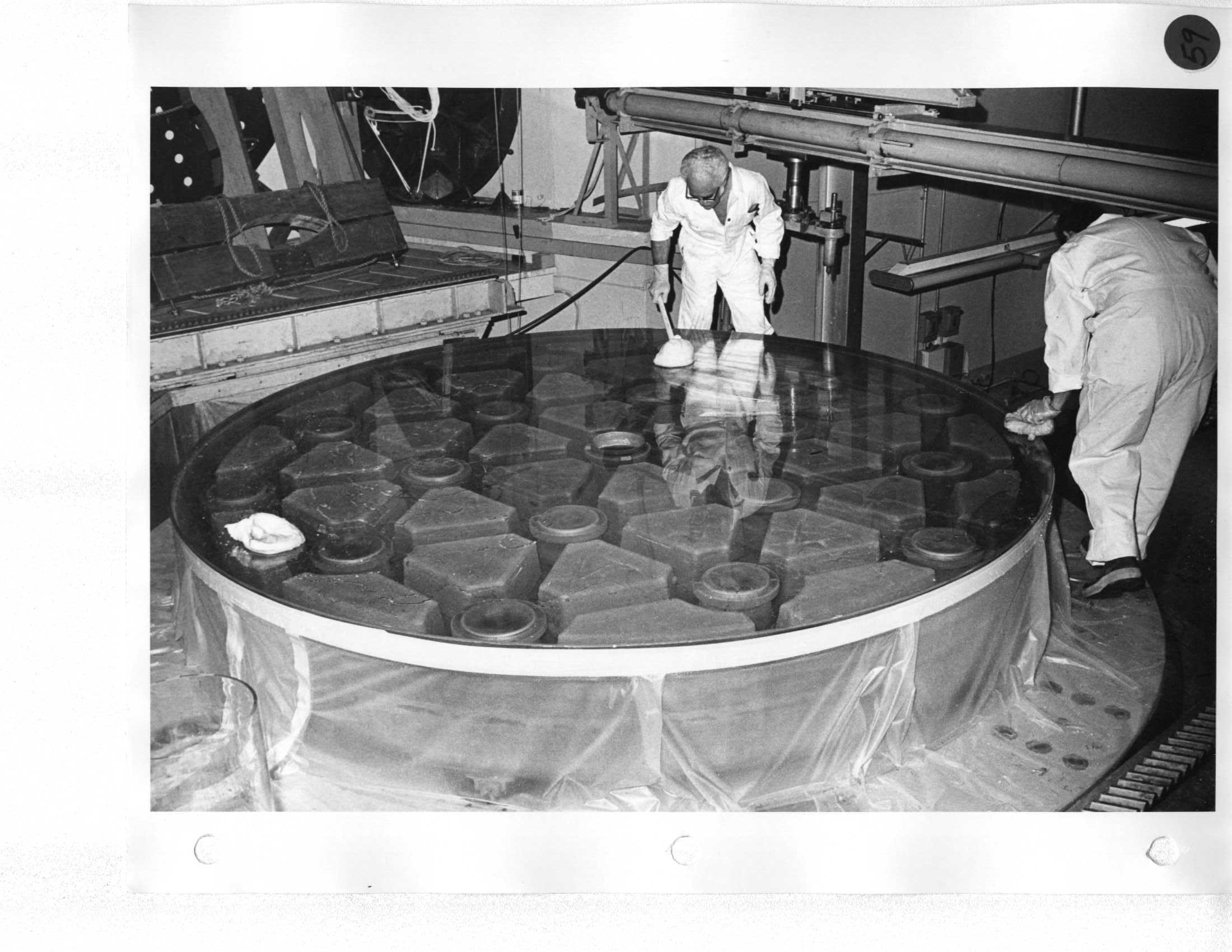 Howard, Ron |
Day 3 Install PVC drain plug in center of mirror from bottom, inflate inner tube, and connect three hangers. |
|
60 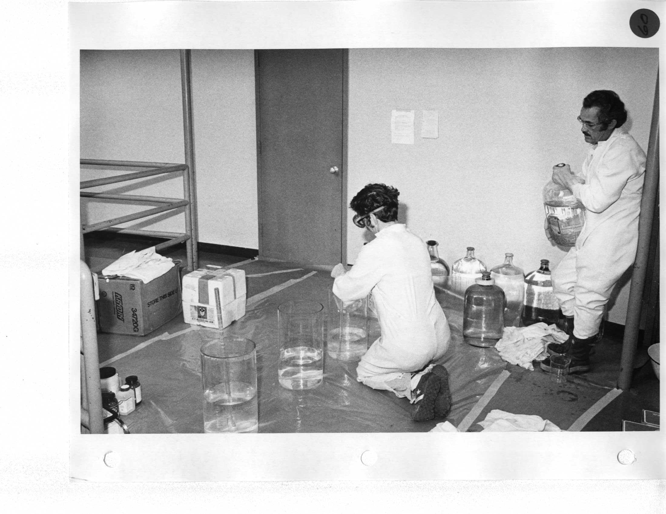 Keith, Ron |
Day 3 Tie balls of cotton on end of PVC tubing (2' long). |
Day 7 Remove split wood blocks. |
61  Ron, De |
Day 3 Optician and technician proceed with stripping (Green Death or sodium hydroxide). |
|
62 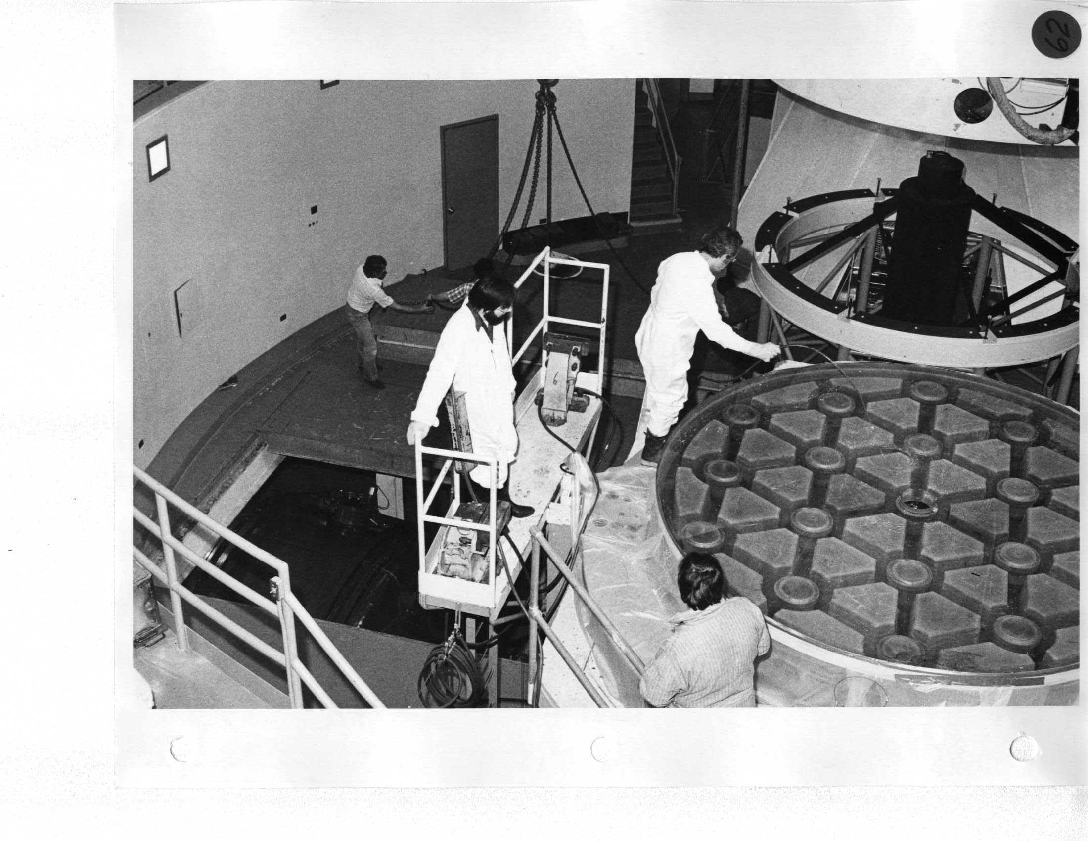 Mike, Neal, Ron |
Day 3 Rinse and wipe dry with cotton towels. |
|
63 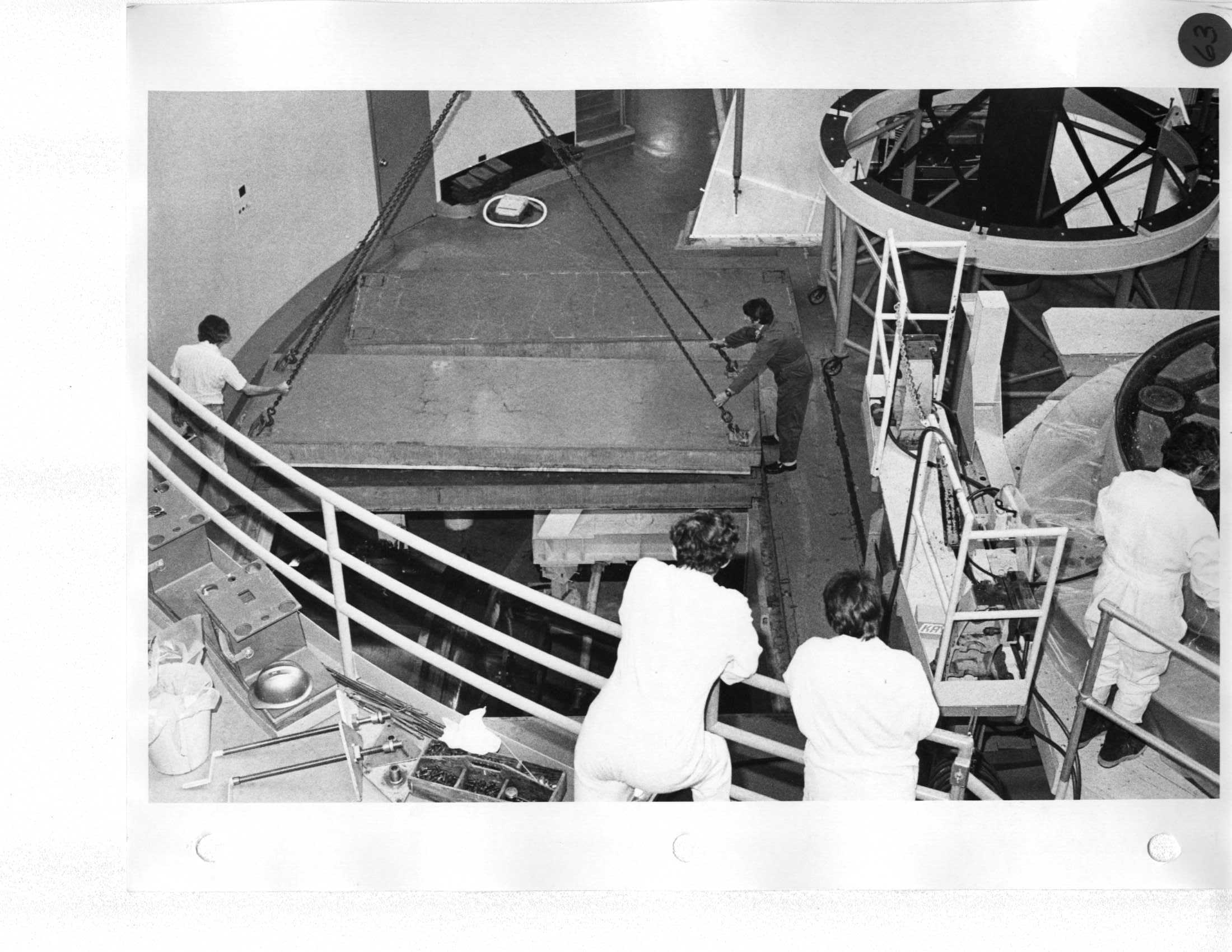 Keith, Erich, De, Ron |
Day 3 Carefully cover with strips of cellophane and tape to side of glass. Lift mirror and cell from optics shop and transfer to mirror handling platform. |
|
64 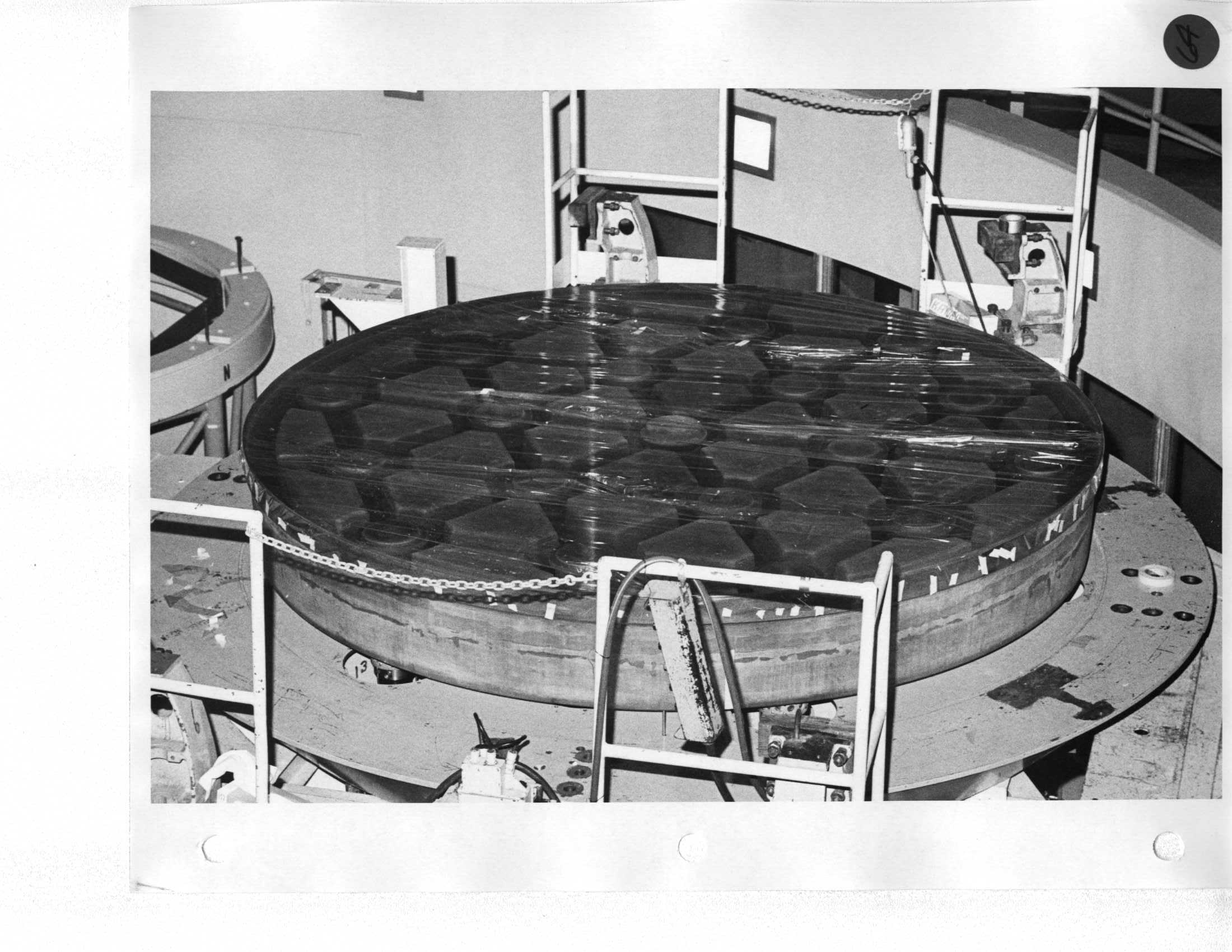 |
Day 3 Carefully cover with strips of cellophane and tape to side of glass. Lift mirror and cell from optics shop and transfer to mirror handling platform. |
|
65 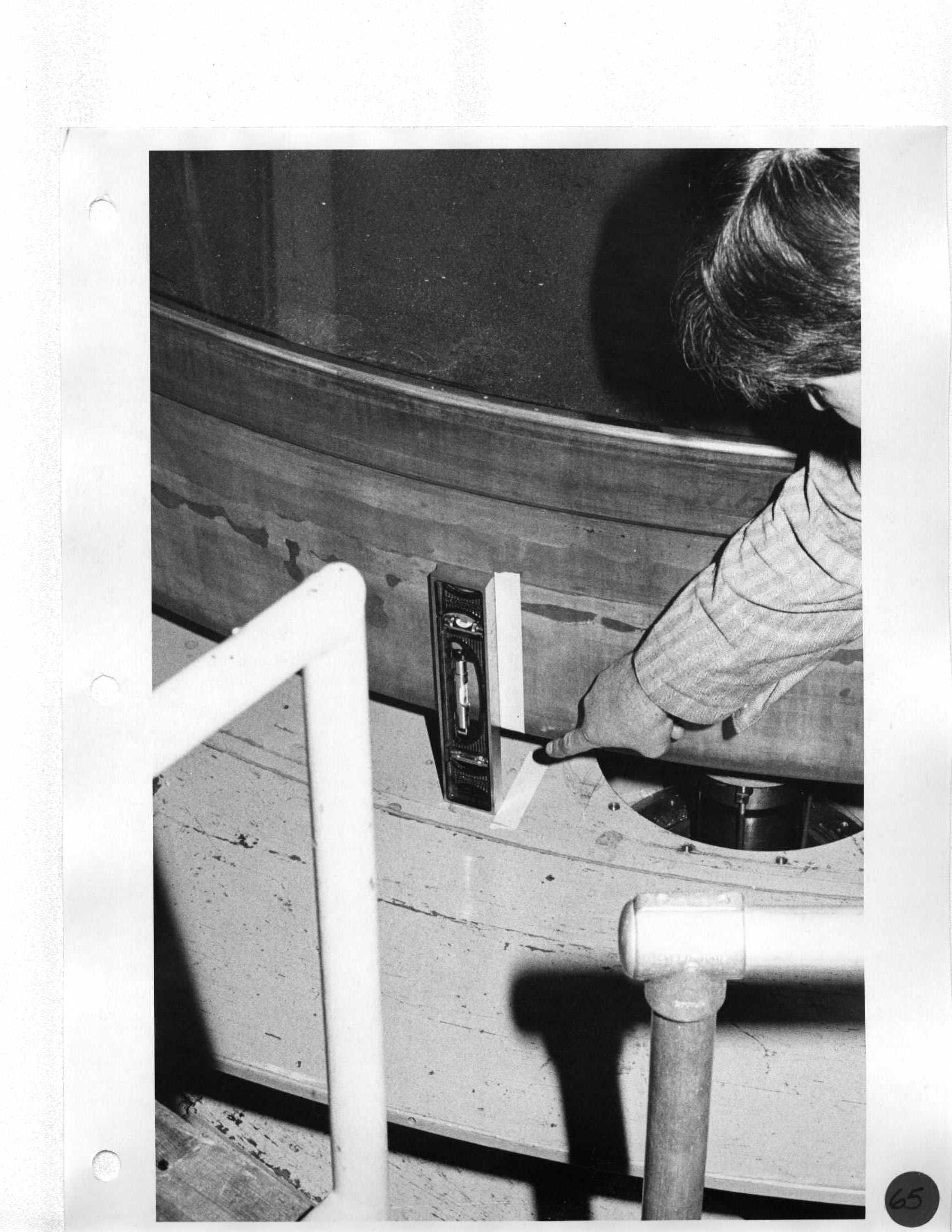 Erich |
Day 3 Don't relax lifting sliings until all eight bolts and nuts (7/8" NF x 2-1/2") are in position; use pin bar for alignment. |
|
66 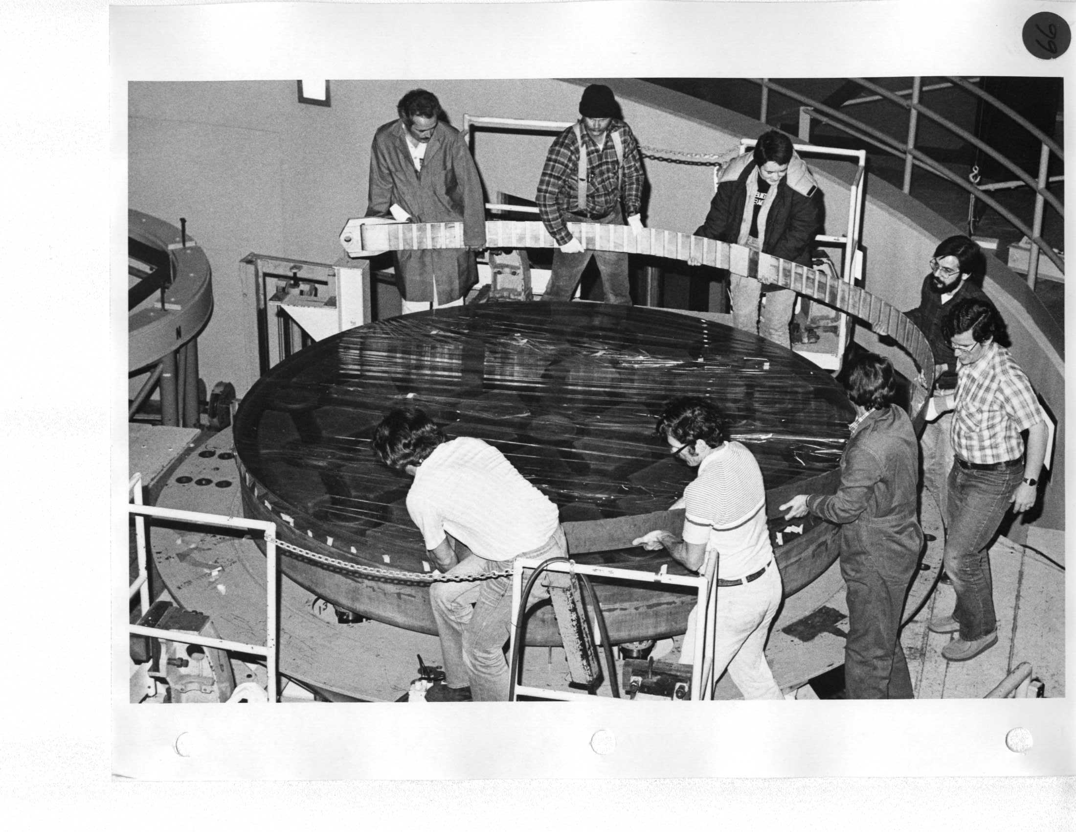 Ron, Keith, De, Erich, Mike, Barry Alcott |
Day 3 |
Day 7 Install mirror supports and remove edge arcs. |
67 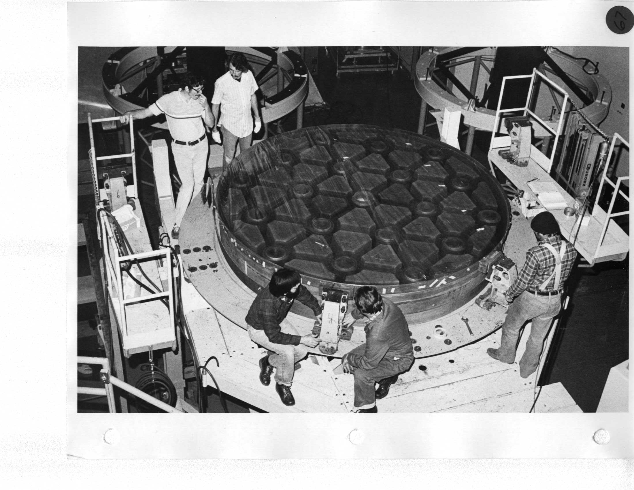 Keith, Mike, Erich |
Day 4 Remove the two defining units after steps A and B; note settings. |
Day 7 Intall both defining units: A. Turn graduated screws clockwise 35 turns to previous setting. B. Lower three mirror jacks with 1/2" key stock and crescent wrench. |
68  |
Day 4 A. Locate 3-1/4" slotted cheese-head screws; screw in by hand until you feel resistance. This keeps crowns from floating. B. Remove three round counterweights from each support with 7/8" open end wrench at the cast iron lever arm bracket. Don't move weight on shaft. All are match-marked. |
Day 7 Release three 1/4" slotted cheese-head screws (crown supports). |
69  Mike, Erich, Neal |
Day 4 A. Loosen two of four radial set screws on large circular flange (those not painted red). Use L-shaped 1/4" allen wrench. Do NOT touch radial centering screws in triangular grey casting! B. Remove all socket head cap screws holding large round flange, EXCEPT the second one, clockwise of the triangular point of the center plate. C. Remove three socket head cap screws, one from each point of the triangle shaped plate supporting the counterweight. |
Day 7 A. Lightly tighten three cap screws and remove jacks. B. Finish installing cap screws on large flange. |
70  Howard, Mike, Erich, Len, Neal |
Day 4 A. Remove two aluminum clips from under 2-1/2" socket head spring-loaded guide pins. If the heads do not bottom out, take hold of 2 of 3 rectangular-shaped counterweights and push up on one while rattling the other back and forth until bolts drop in place. B. Install three hex-shaped and relieved extension screws and traingular push plate for jack. Use three holes in triangle casting. |
Day 7 |
71  Neal, Erich |
Day 4 A. Remove three remaining cap screws from counterweight assembly flange. B. Lower flange down 3" above mirror cell and install three clamps with slotted studs hanging down through three easily-accesible holes; add bent bracket and nut. C. Continue to lower flange until it is flush with mirror cell; using screwdriver, rotate three slotted studs to engage clamps with outer diameter of hole, and tighten with 12/16" open-end wrench. |
|
72 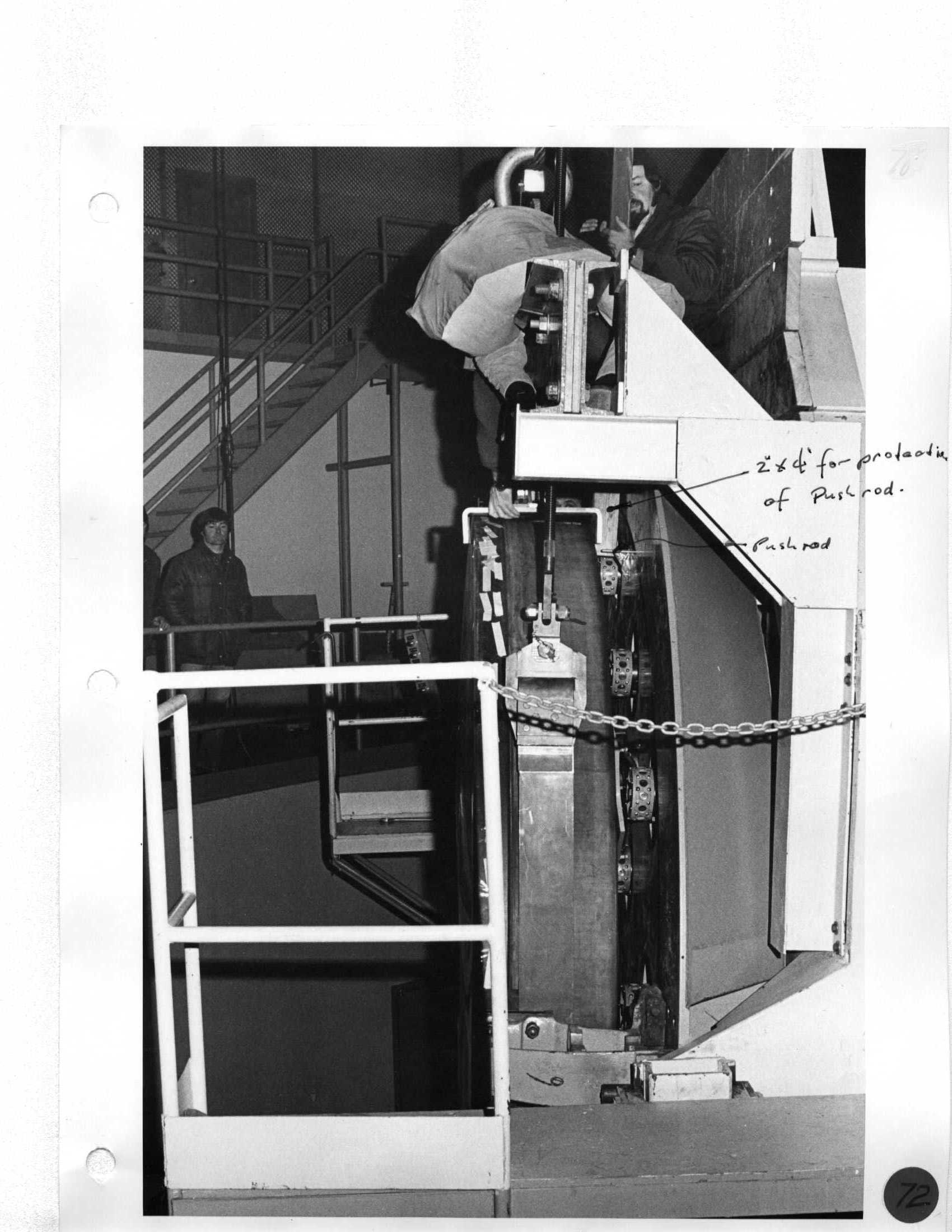 Neal |
Day 4 A. Install three long 1/2" extensions in first hole clockwise of triangular plate. NOTE: Center support has not triangle plate. B. Install jack and align screw push-plate by adjusting three nuts supporting jack; screw pilot and bearing to engagement with push-plate. |
|
73 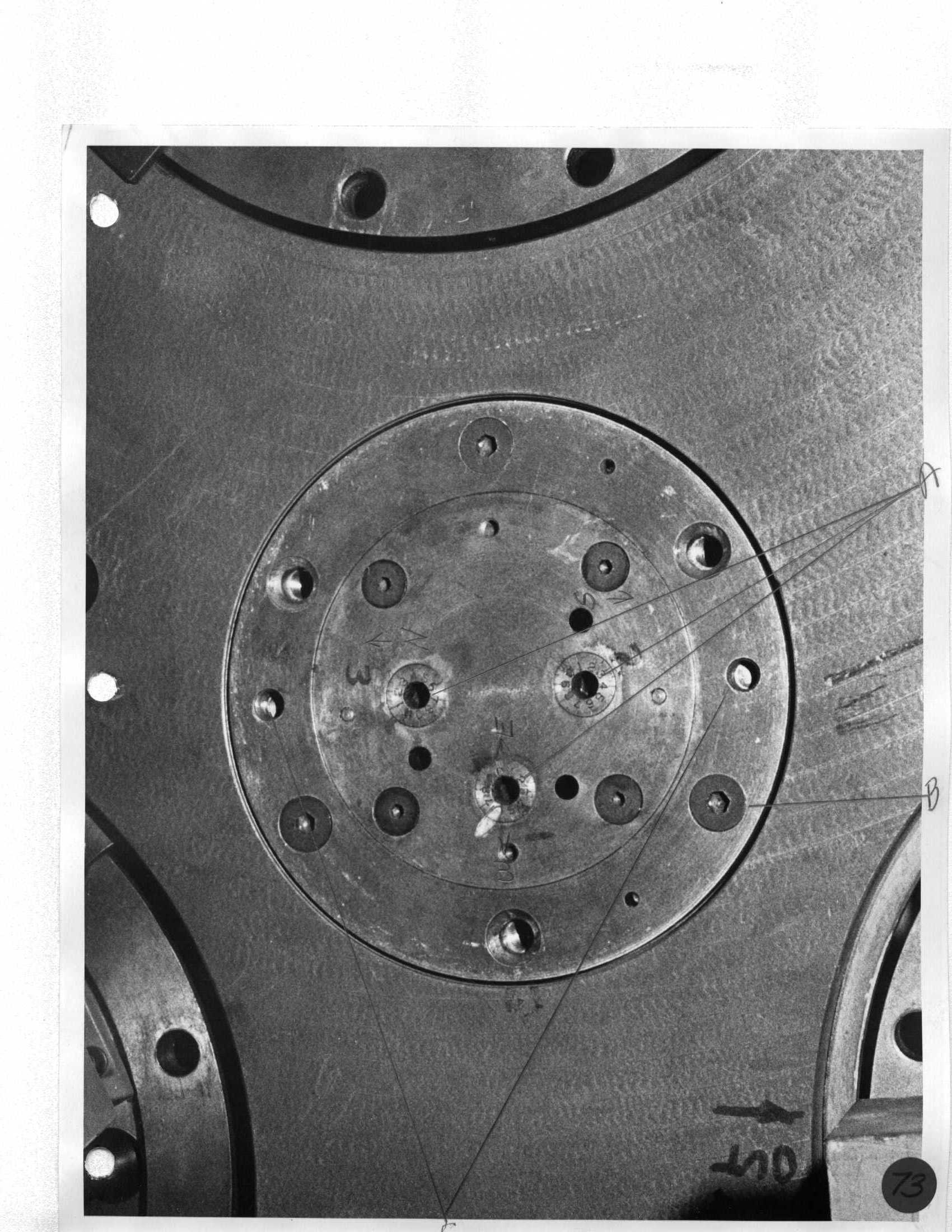 |
Day 4 Install split wood keepers (nails down) around 1" shaft supporting large 70-lb counterweight, and push up into hole in plate. |
|
74 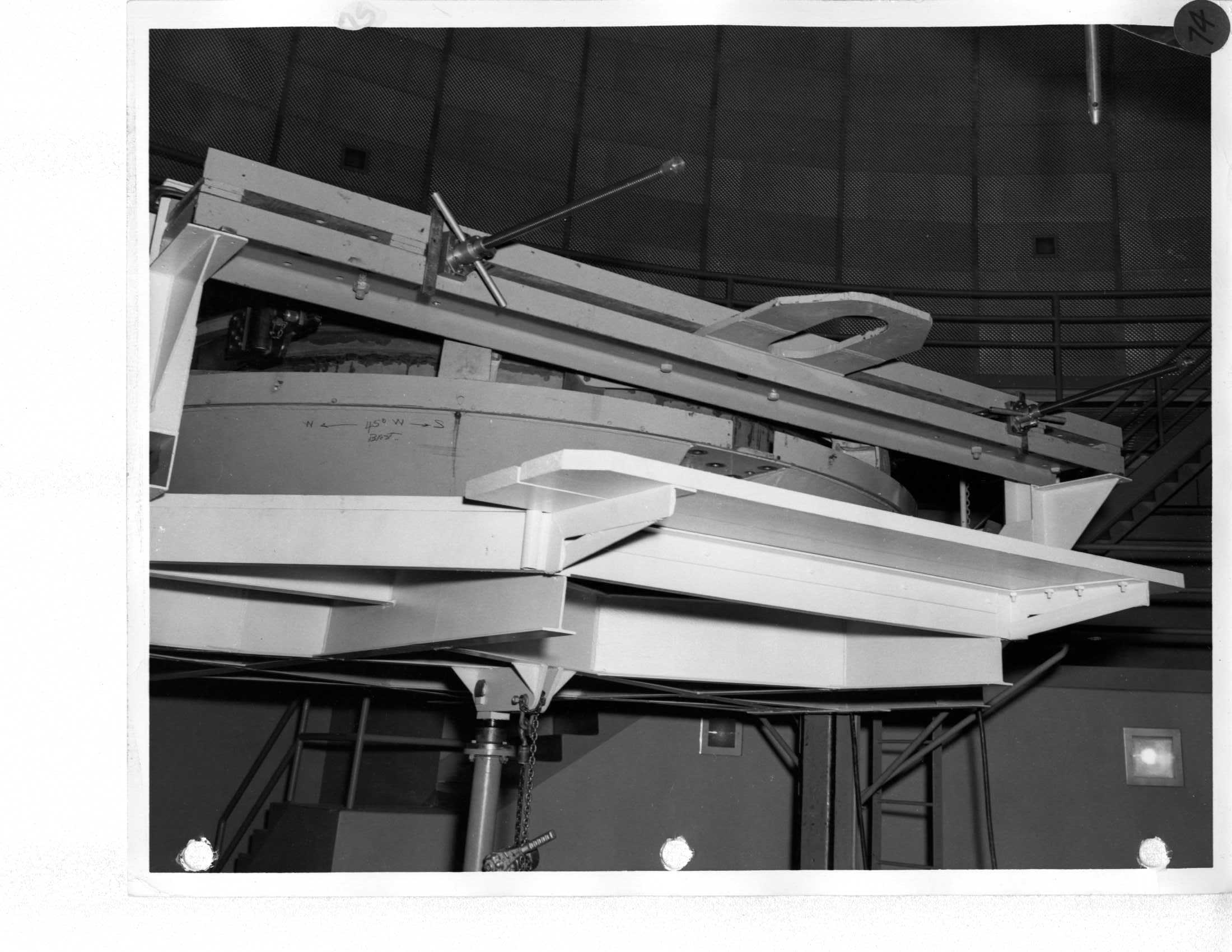 |
Day 5 Use long 2" stinger to intall lifting bar. |
|
75 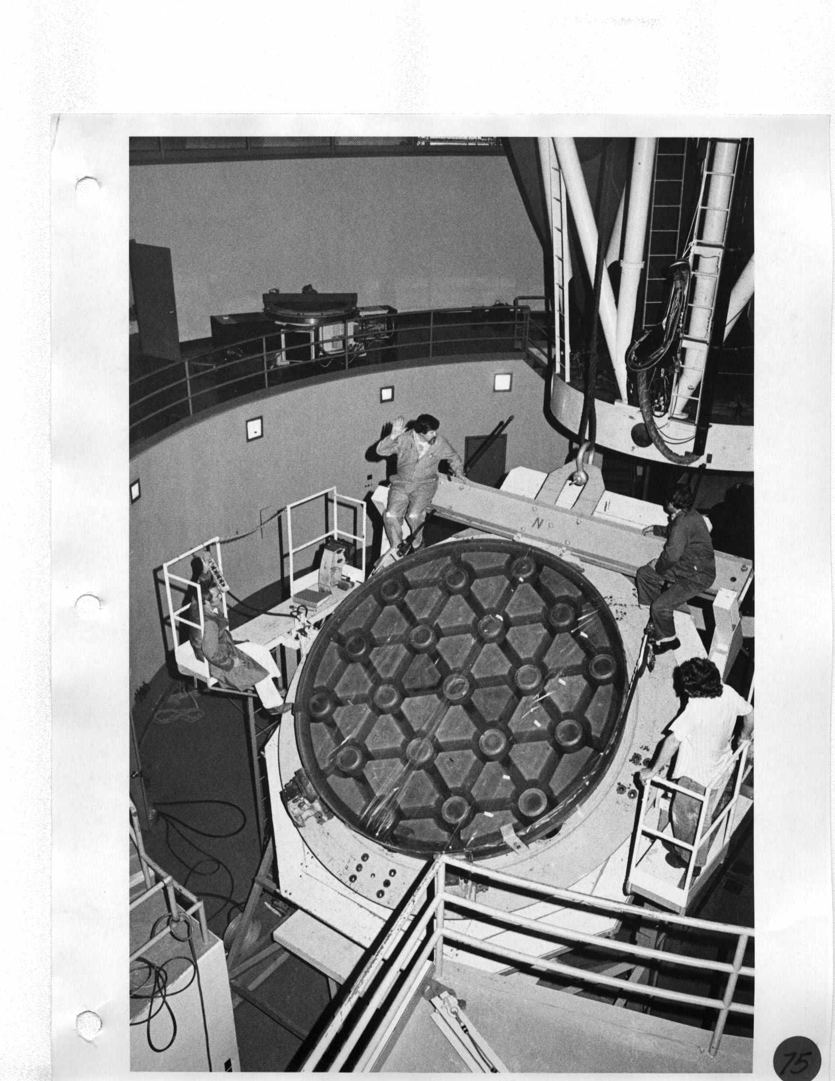 Ron, Neal, Erich |
Day 5 A. Use long 2" stinger to intall lifting bar. B. Take up sling screw jacks until mirror starts to move. |
Day 8 Stow platform; remove spreader bar support arms. Day 6 DO NOT move platform until three mirror supports have been installed (Center, East, West). |
76 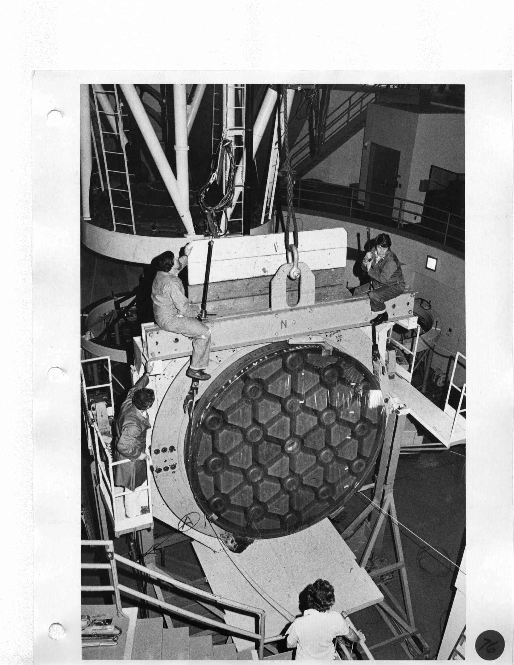 Ron, Neal, Erich |
Day 5 Slip sling around mirror through edge arcs and support with aluminum brackets attached to edge arcs. (6 technicians.) |
Day 6 Remove mirror sling and cover mirror with plywood. |
77 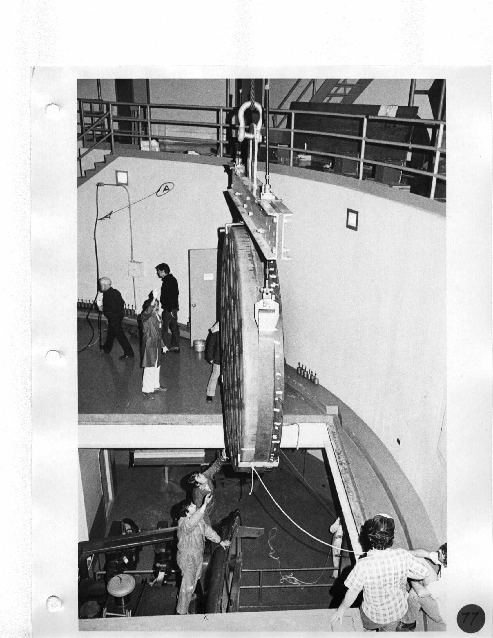 Howard, Ron, Neal, Rem Stone, Erich |
Day 5 Slip sling around mirror through edge arcs and support with aluminum brackets attached to edge arcs. |
|
78 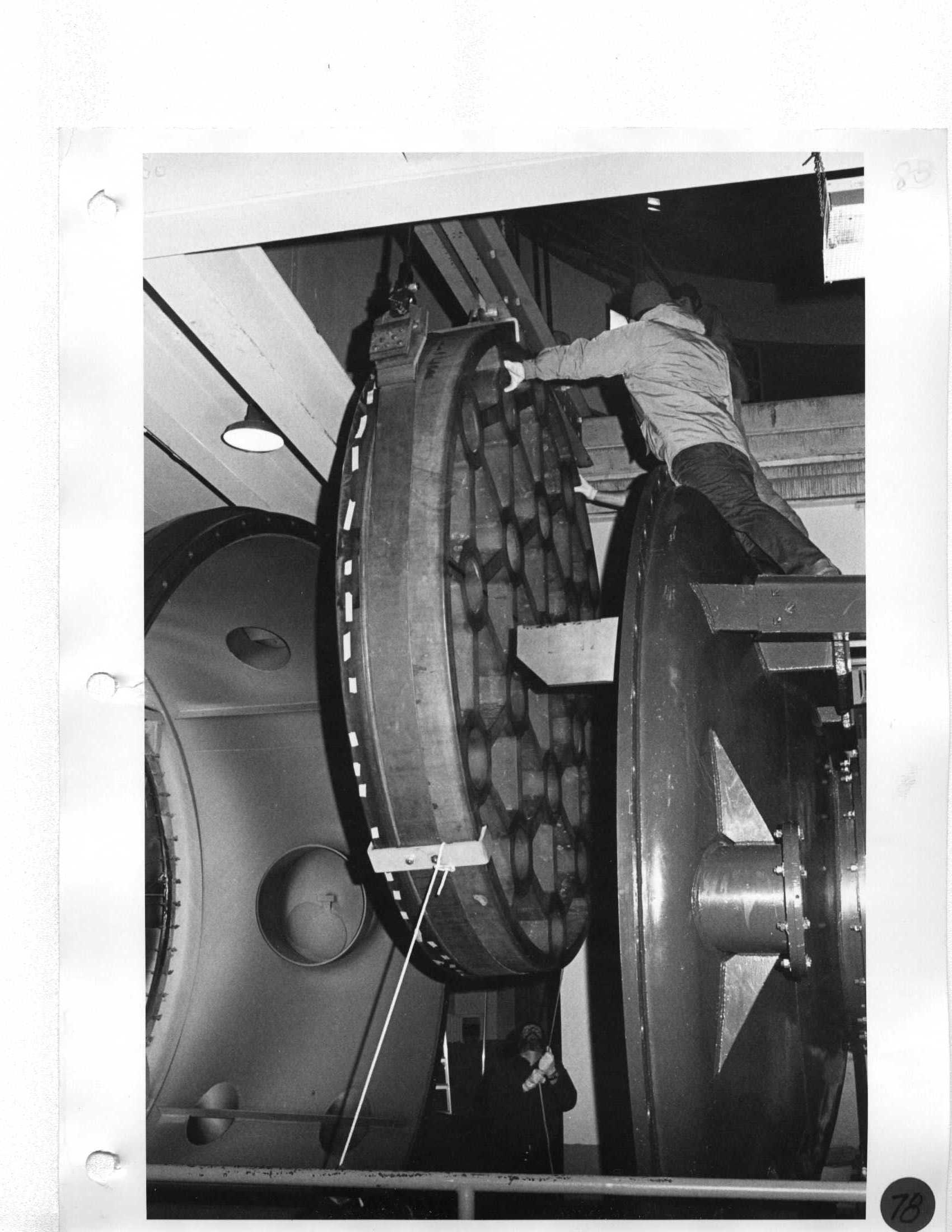 Erich |
Day 5 Install top U-shaped safety bracket on spreader bar (tapped holes next to aluminum surface) and two safety brackets on sling. |
|
79 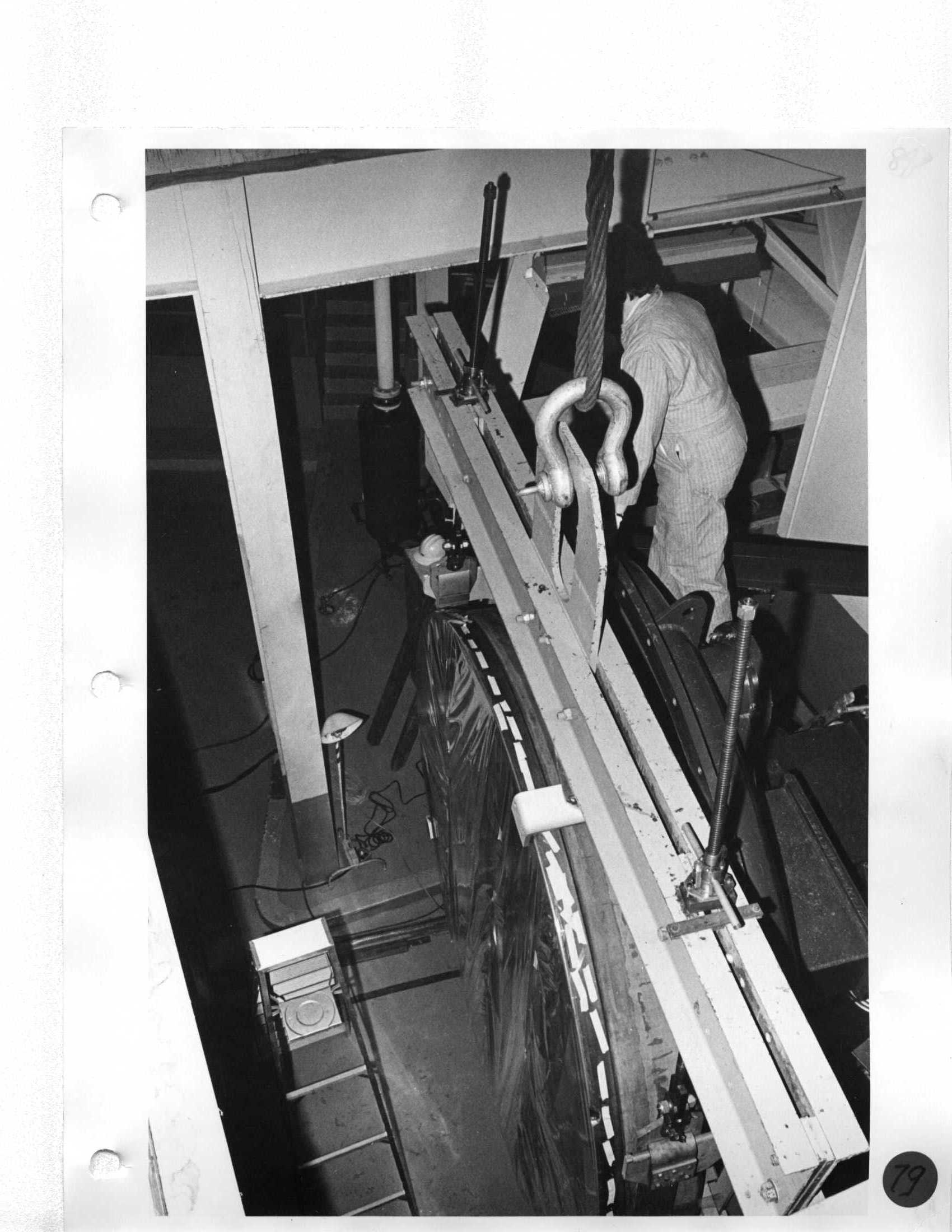 Neal |
Day 5 As platform is tilted, keep bridge crane hook snug on lifting bar and back off Tuggit hoist. |
|
80  Ron, Howard, Erich, Neal |
Day 5 After mirror is in vertical position, lift mirror 1/4" off edge arcs so that lifting bar clears support arms. |
|
81 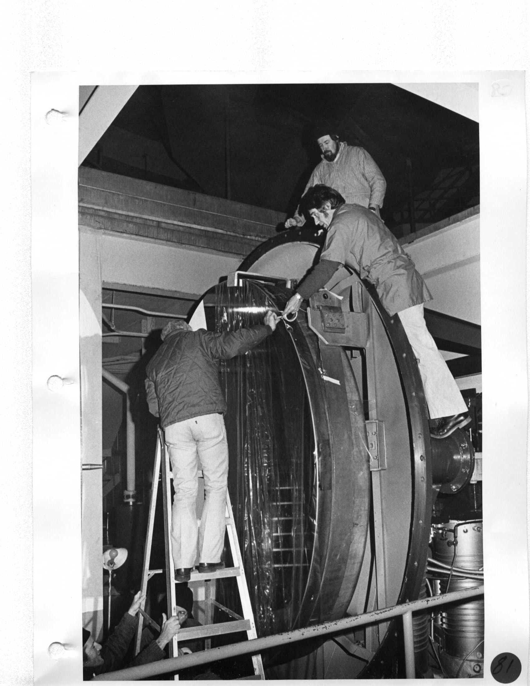 Ken, Howard, Erich, Neal |
Day 5 Roll platform away from mirror. |
|
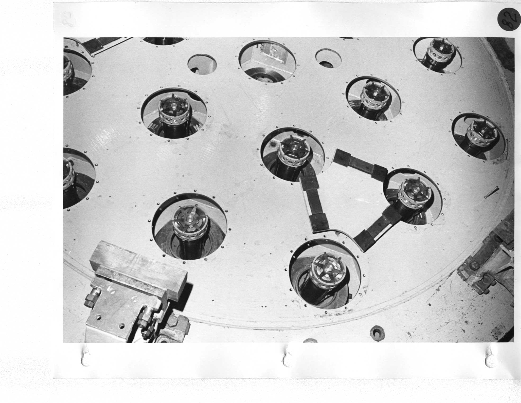
82 |
Day 5 Rotate dome and position mirror over tank. |
|
83  Erich |
Day 5 Lower mirror enough to clear support arms and slide sling west into position; place weight on tank supports. |
|
84 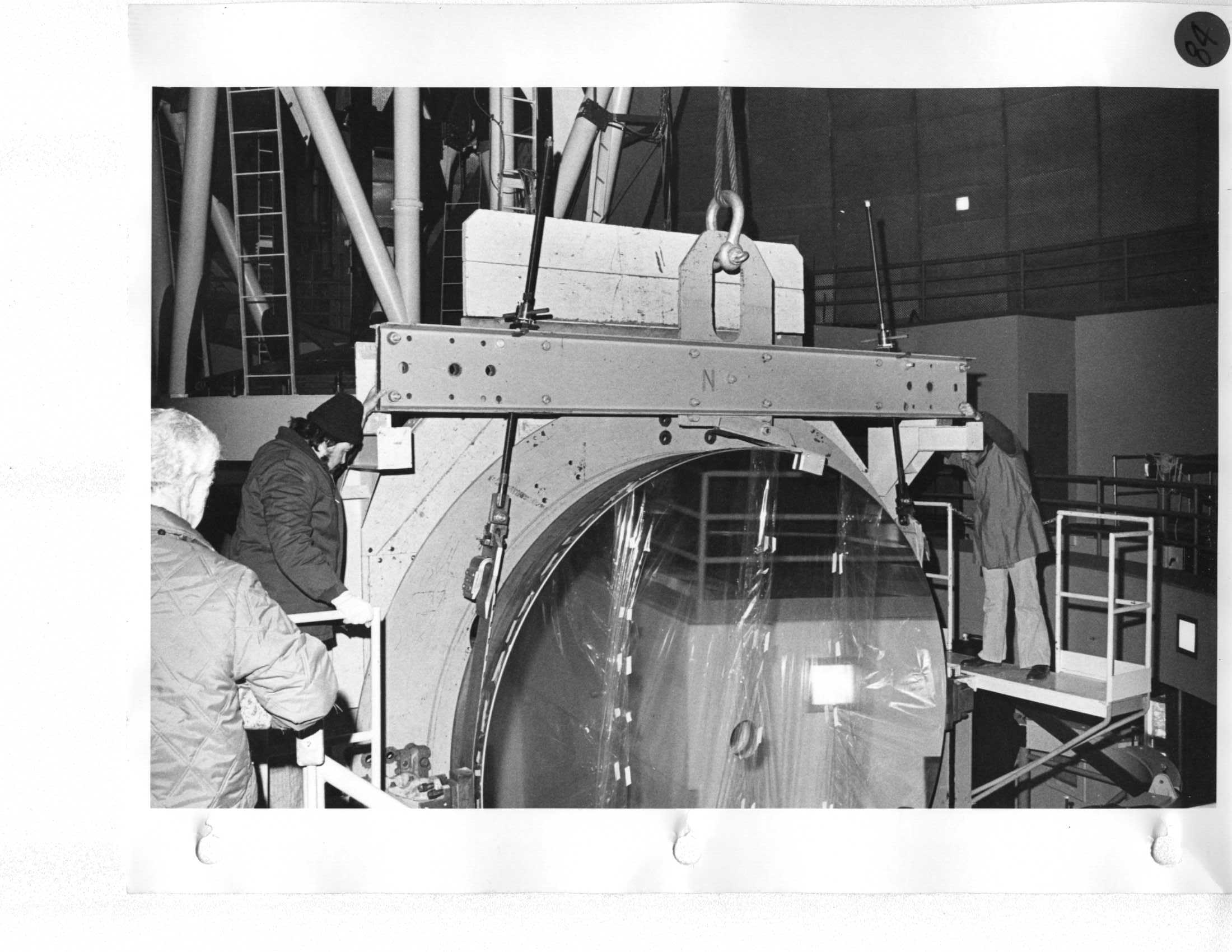 Howard, Neal, Erich |
Day 5 |
|
85 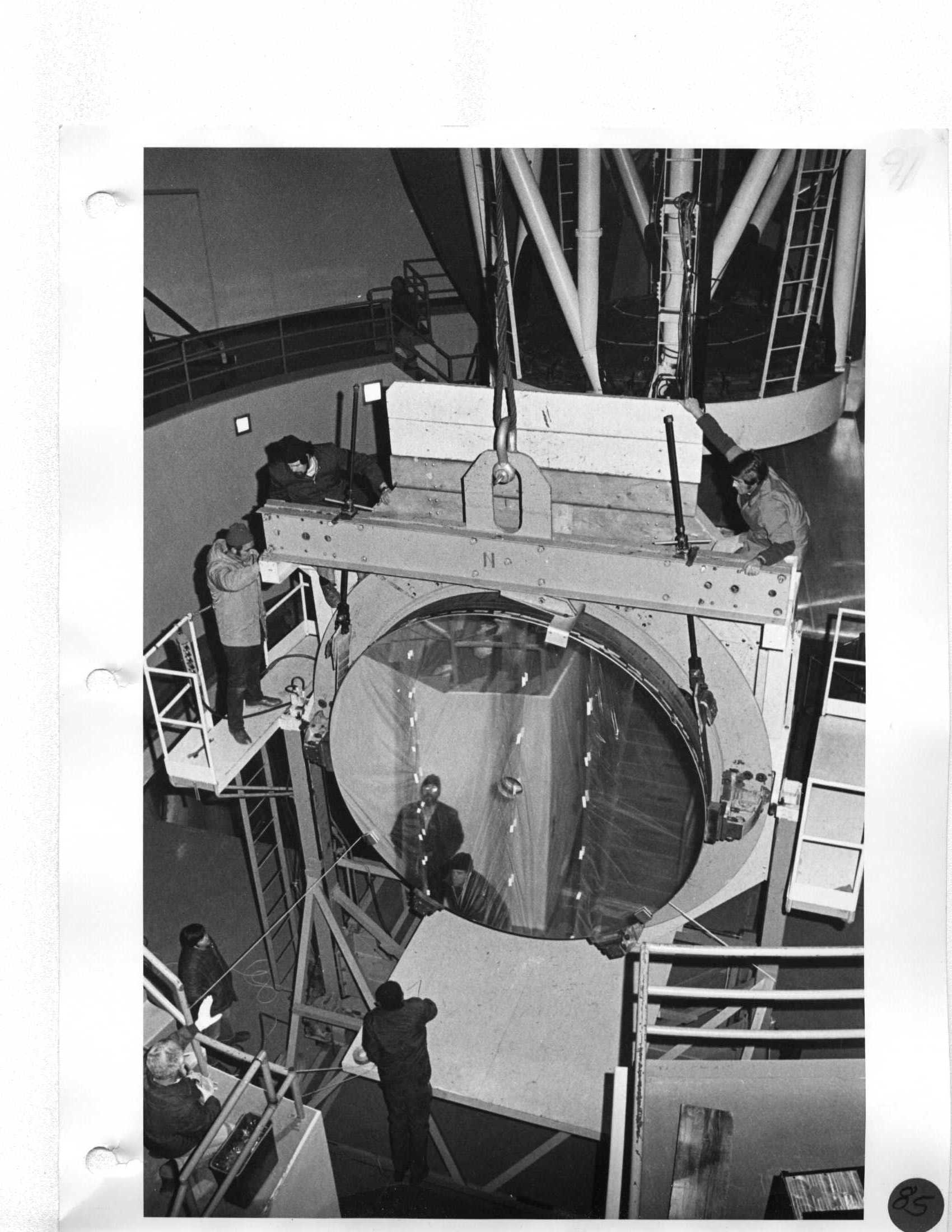 Howard, Ron, Neal, Ken, Erich |
Day 5 Remove all cellophane and allow optician to make final inspection of mirror. |
Day 6 Open tank and cover surface of mirror with cellophane. |
86 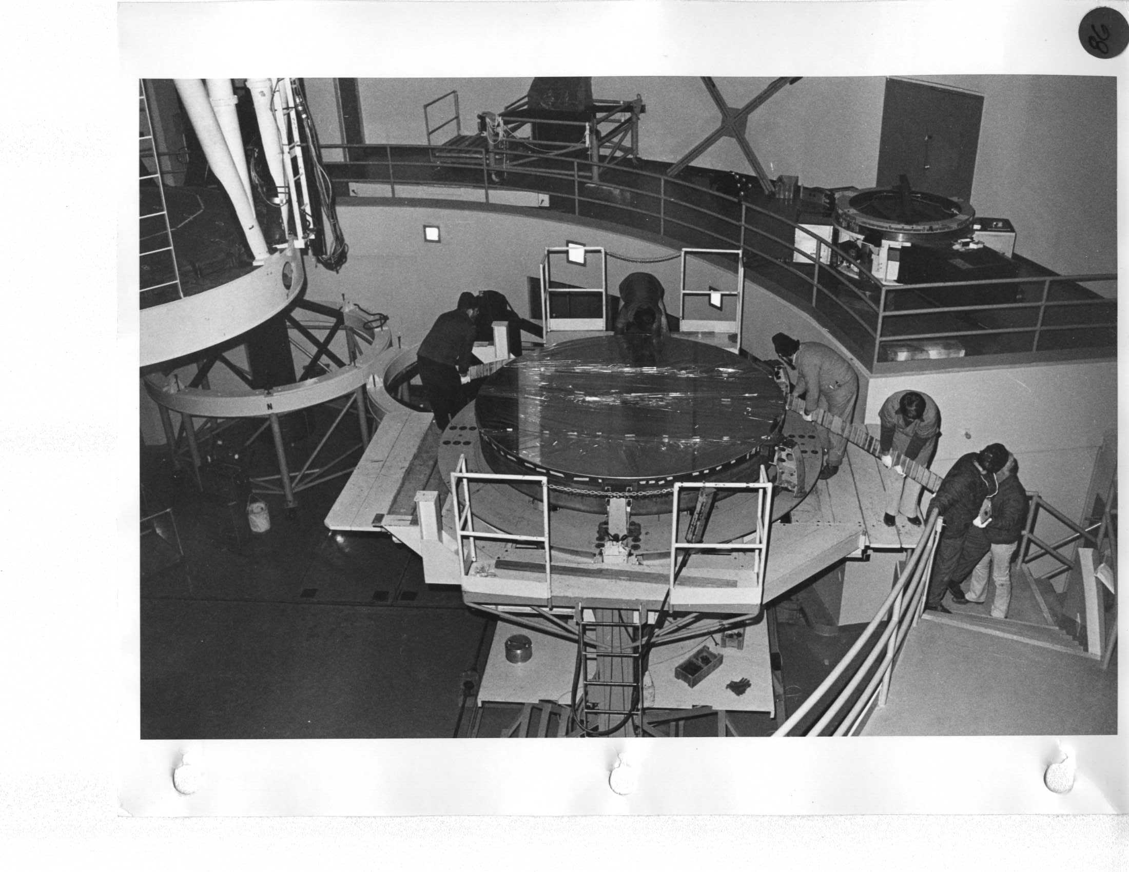 Neal, Erich, Howard |
Day 5 Thoroughly inspect all crowns for damage. |
|
ALLOW ONE DAY TO ALUMINIZE |
||